■目次
■ 1. 概要
B3Dオブジェクトはテクスチャつきのオブジェクトを作成出来ます。作成したオブジェクトは路線のストラクチャーや車両オブジェクトに用いる事が出来ます。個別のオブジェクトは複数のポリゴンが内包されます。このファイルフォーマットは複数のポリゴンを[MeshBuilder]セクションにおいて色かテクスチャ情報を其々のセクションにおいて設定できます。これにより、いくつかの共通の[MeshBuilder]セクションの属性を用いて複数のポリゴンを生成できます。個別のポリゴンはこのファイルフォーマットにおいてはfaceと呼ばれます。
ファイルは任意のエンコードで記述されたプレーンテキストですがencoding、好ましい選択としてはバイトオーダー付きのUTF-8です。 parsing model に用いる数字は ルーズですが、 それでも出力にあたっては 厳密な 出力をすることが望ましいです。 ファイル名は任意ですが、 拡張子は必ず .b3d を用います。 ファイルは基本的に上から下に向かって解釈されていきます。
➟ B3Dフォーマットのクイックリファレンスも参照してください…
■ 2. 文法
ファイル内のそれぞれの行はコマンド名とその引数に分けられています。全てのコマンドの文法は同様です。
コマンド名 は大文字と小文字を区別せず使えます。 もし引数であった場合、 コマンド名 と 引数1 少なくとも1つ以上の半角スペース(U+0020)で空ける必要があります。 引数は 半角コンマ(U+002C)で区切られます。 命令の前後の ホワイトスペース は、引数の前後、行頭と行末は無視されます。 何もない空白行も同様に、ホワイトスペースとして無視されます。
引数はそれぞれの 引数i を空白にすることで省略することができます。 この場合多くのケースでコマンド固有の既定の値が適用されます。 コマンド固有の規定値の詳細は使用できるコマンドのセクションで記載されています。 ただし、他の引数が指定されているときは最初の引数は省略できません。
コメントは行末のどこでも使用可能です。 コメントはセミコロン (U+003B)で始まります。 コメントは存在する場合、処理される前に全ての行から削除されます。
■ 3. 使用可能なコマンド
このコマンドは新しい face のセクションの始まりを記します。 以下に続くコマンドの前に、これを記しておかなければなりません。 オブジェクトファイルには、必要に応じていくつでも [MeshBuilder] セクションを設置できます。 全てのこれに続くコマンドは、最後に開かれた [MeshBuilder] コマンドに関連付けられます。
nY: この頂点における法線のY座標をメートルで記します。 デフォルト値は0です。 nZ: この頂点における法線のZ座標をメートルで記します。 デフォルト値は0です。
このコマンドは Face もしくは Face2 コマンドを用いた面に用いるための新しい頂点を作成できます。 必要に応じて [MeshBuilder] セクション内には Vertex コマンドをいくつも用いることができます。 ただし、頂点の設置順序は他のコマンドに影響を与えるため重要な要素です。 最初の頂点はインデックス番号0、 続く頂点は、1,2,3…等と順番に与えられていきます。
法線の方向は面の特定の場所において垂直方向です。 もしすべての頂点の面が全く同じ法線である場合、 法線はフラットに見えます。 もし適切に用いられているならば、 頂点ごとに異なる法線を設定することで、まるで曲がった面をしているかのような錯覚を与えることができます。 しかし複数の面にわたって - 同一の空間座標上の全ての頂点で同一の法線を用いると、 もしすべて0が設定されていた場合は、法線は自動的に計算されます。
このコマンドは任意の長い頂点のリストで面を生成します。 インデックス番号は、先にVertexコマンドにより生々された純序に従い生成されます。 したがって、 Face コマンドは Vertexコマンドの後に記述する必要があります。 最初の Vertex コマンドはインデックス番号0で生成され、 そしてそれ以降の Vertex コマンドは 1, 2, 3 などとインデックス番号を生成します。 頂点のインデックス番号の記述順序は重要で、面に正対して時計回りに記述する必要があります。 生成された面の後側は何も見えないでしょう。 しかし、 Face2 コマンドでなら両面が見える面を作成することができます。 凸面の頂点ポリゴンのみサポートされます。
このコマンドは任意の長い頂点のリストで面を生成します。 インデックス番号は、先にVertexコマンドにより生々された純序に従い生成されます。 したがって、 Face コマンドは Vertexコマンドの後に記述する必要があります。 最初の Vertex コマンドはインデックス番号0で生成され、 そしてそれ以降の Vertex コマンドは 1, 2, 3 などとインデックス番号を生成します。 頂点のインデックス番号の記述順序は重要で、面に正対して時計回りに記述する必要があります。 後ろ側の面も同様に見えますが、 後側の面に対する光の当たり方は表側の面と同一になります。 凸面の頂点ポリゴンのみサポートされます。
HalfDepth: 浮動小数点数で、立方体の奥行きの半分の長さを メートル で表します。
このコマンドは HalfWidth 、 HalfHeight 、 HalfDepth で指定された大きさの三次元の立方体を生成します。 生成される立方体の中心は原点 (0,0,0) です。 したがって、 X軸上では -HalfWidth から HalfWidth に拡張し、 Y軸上は -HalfHeight から HalfHeight に、そしてZ軸上は -HalfDepth to HalfDepthに拡張します。 生成される立方体は常に8つの頂点と6つの面を持ちます。
Cube の表記方法について
Cube コマンドは、一連の Vertex と Face コマンド群を実行することに相当します。 この時同じ [MeshBuilder] セクション内において他のコマンドと同時に実行する際に考慮する必要があります。 Cube コマンドの詳細は こちらにあります。
This command creates a frustrum. If LowerRadius and UpperRadius are equal, the object generated will reduce to a prism, which can be used as an approximation to the cylinder. If either LowerRadius or UpperRadius are zero, the object generated will reduce to a pyramid. The frustum will be centered on the origin (0,0,0). On the x- and z-axes, the frustum extends from -LowerRadius to LowerRadius for the lower base and from -UpperRadius to UpperRadius for the upper base. On the y-axis, the frustum extends from -1⁄2*Height to 1⁄2*Height.
The number of vertices n will usually suffice to be 6 or 8 when only small radii are used, for example to create a pole. Regardless of the values of UpperRadius, LowerRadius and n, the frustum will always have 2*n vertices, and usually n+2 faces unless any of the caps are omitted. If UpperRadius or LowerRadius are negative, the absolute value is being taken, but the respective caps are not created. If Height is negative, the roles of top and bottom are reversed and the faces will be visible from the inside, while otherwise, they will be visible from the outside.
Cylinder representation
The Cylinder command is equivalent to a series of Vertex and Face commands, which you need to account for when using other commands in the same [MeshBuilder] section. The details on what the Cylinder command does are available here.
このコマンドは、 OpenBVE によって無視されます。
TranslateAll X, Y, Z
Y: A floating-point number representing the translation on the y-coordinate in meters. Negative values translate down, positive ones up. The default value is 0.
Z: A floating-point number representing the translation on the z-coordinate in meters. Negative values translate backward, positive ones forward. The default value is 0.
The Translate command moves all vertices that have been created so far in the [MeshBuilder] section via the Vertex, Cube or Cylinder commands. Subsequent vertices are not affected. You can use as many Translate commands as desired in a [MeshBuilder] section. The TranslateAll command not only affects the vertices generated in the current [MeshBuilder] section, but also those created in previous [MeshBuilder] sections. This is useful to insert at the end of the file in order to translate the whole object.
ScaleAll X, Y, Z
Y: A non-zero floating-point number representing the scale factor on the y-coordinate. The default value is 1.
Z: non-zero A floating-point number representing the scale factor on the z-coordinate. The default value is 1.
The Scale command scales all vertices that have been created so far in the [MeshBuilder] section via the Vertex, Cube or Cylinder commands. Subsequent vertices are not affected. You can use as many Scale commands as desired in a [MeshBuilder] section. The ScaleAll command not only affects the vertices generated in the current [MeshBuilder] section, but also those created in previous [MeshBuilder] sections. This is useful to insert at the end of the file in order to scale the whole object.
RotateAll X, Y, Z, Angle
Y: The y-direction of the rotational axis. Negative values point down, positive ones up. The default value is 0.
Z: The z-direction of the rotational axis. Negative values point backward, positive ones forward. The default value is 0.
Angle: The angle to rotate in degrees. Negative values rotate counter-clockwise, positive ones clock-wise. The default value is 0.
The Rotate command rotates all vertices that have been created so far in the current [MeshBuilder] section via the Vertex, Cube or Cylinder commands. Subsequent vertices are not affected. The axis of rotation is specified via the X, Y and Z values. Rotation will occur in the plane perpendicular to that direction. A zero vector for this axis is treated as (1,0,0). All other directions are normalized. You can use as many Rotate commands as desired in a [MeshBuilder] section. The RotateAll command not only affects the vertices generated in the current [MeshBuilder] section, but also those created in previous [MeshBuilder] sections. This is useful to insert at the end of the file in order to rotate the whole object.
ShearAll dX, dY, dZ, sX, sY, sZ, Ratio
dY: The y-coordinate of the vector D. The default value is 0.
dZ: The z-coordinate of the vector D. The default value is 0.
sX: The x-coordinate of the vector S. The default value is 0.
sY: The y-coordinate of the vector S. The default value is 0.
sZ: The z-coordinate of the vector S. The default value is 0.
r: The ratio that indicates how much to displace vectors. The default value is 0.
The Shear command performs a shear mapping for all vertices that have been created so far in the current CreateMeshBuilder section. The ShearAll command not only affects the vertices generated in the current CreateMeshBuilder section, but also those created in previous CreateMeshBuilder sections. This is useful to insert at the end of the file in order to shear the whole object.
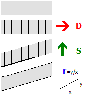
The shear mapping is performed around the origin. Loosely speaking, the object is sliced into planes along the direction D and then displaced along the direction S. Typically, D and S are perpendicular. D and S are always normalized. If Ratio is 0, no transformation is performed. If D and S are perpendicular, a Ratio of 1 corresponds to a slope of 45 degrees.
MirrorAll X, Y, Z
Y: Whether the y-axis should be mirrored. The default value is 0 (false).
Z: Whether the z-axis should be mirrored. The default value is 0 (false).
The Mirror command mirrors all vertices that have been created so far in the current CreateMeshBuilder section via the AddVertex, Cube or Cylinder commands. Subsequent vertices are not affected. The direction(s) to mirror are specified via the X, Y and Z values. You can use as many Mirror commands as desired in a CreateMeshBuilder section.
The MirrorAll command not only affects the vertices generated in the current CreateMeshBuilder section, but also those created in previous CreateMeshBuilder sections. This is useful to insert at the end of the file in order to mirror the whole object.
ColorAll Red, Green, Blue, Alpha
Green: The green component of the color. Measured from 0 (black) to 255 (green). The default value is 255.
Blue: The blue component of the color. Measured from 0 (black) to 255 (blue). The default value is 255.
Alpha: The alpha component of the color. Measured from 0 (transparent) to 255 (opaque). The default value is 255.
The Color command sets the color for all faces that were already created in the current [MeshBuilder] section. If no texture is used, the faces will be colored using the color data as specified by Red, Green and Blue. If a texture is used, the pixels in the texture will be multiplied by the color, where multiplying with black results in black and multiplying with white does not change the color of the texture pixels. Values in-between make the texture pixels darker. When lighting is used in the route, the actual color can change depending on the lighting conditions, but will usually become darker.
The ColorAll command sets the color for all faces that were already created in the current [MeshBuilder] section, and those created in the previous [MeshBuilder] sections.
EmissiveColorAll Red, Green, Blue
Green: The green component of the color. Measured from 0 (black) to 255 (green). The default value is 0.
Blue: The blue component of the color. Measured from 0 (black) to 255 (blue). The default value is 0.
The EmissiveColor command sets the emissive color for all faces that were already created in the current [MeshBuilder] section. The difference between the Color command and the EmissiveColor command is that the Color command is affected by lighting, while the EmissiveColor command is not. Thus, the EmissiveColor command should be used for faces which would emit light themselves, including signals, lamps, windows and the like. The actual color contribution to the faces will be the sum of the light-affected color data and the static emissive color data.
The EmissiveColorAll command sets the color for all faces that were already created in the current [MeshBuilder] section, and those created in the previous [MeshBuilder] sections.
GlowHalfDistance: The distance at which the glow is at 50% of its intensity, measured in meters. The value must be an integer in the range from 1 to 4095, or 0 to disable glow attenuation. The default value is 0.
GlowAttenuationMode: The glow attenuation mode to use. The default is DivideExponent4.
▸ Available options for BlendMode:
Additive: The faces are rendered additively.
▸ Available options for GlowAttenuationMode:
DivideExponent4: The glow intensity is determined via the function x4 / (x4 + GlowHalfDistance4), where x is the distance from the camera to the object in meters.
This command sets the blend mode for all faces in the current [MeshBuilder] section. The Normal mode replaces screen pixels with texture pixels. The Additive mode adds the color of texture pixels to the color of screen pixels, where adding black does not change the screen pixel, while adding white results in white. If GlowHalfDistance is 0, glow attenuation will be disabled, which is the default. If glow attenuation is to be used, GlowHalfDistance represents the distance in meters at which the glow is exactly at 50% of its intensity. When the camera approaches the face, the face will gradually fade out (become transparent). The function used to determine the exact intensity for a given distance can be influenced with the setting of GlowAttenuationMode. DivideExponent2 creates a smoother transition, but will converge to the maximum intensity very slowly, while DivideExponent4 creates a sharper transition which converges more quickly.
▸ Available options for WrapMode:
NighttimeTexture: The file name of the daytime version of the texture to load, relative to the directory the object file is stored in.
This command loads a texture and uses it for all faces in the current CreateMeshBuilder section. The file name is relative to the directory the object file is stored in. You can use PNG, which supports full alpha channels, but use the alpha channel only if absolutely required as it reduces performance. Prefer using a texture without an alpha channel in conjunction with the SetDecalTransparentColor command in order to use color-key transparency.
If NighttimeTexture is used, it specifies the texture to be used on nighttime lighting conditions, while DaytimeTexture then specifies the texture to be used on daytime lighting conditions. The textures might blend into each other and should be designed accordingly. If NighttimeTexture is used, DaytimeTexture must also be specified. If NighttimeTexture is not used, low lighting conditions will make the daytime version darker. Nighttime textures are meant for use with train interior/exterior objects.
Green: The green component of the color. Measured from 0 (black) to 255 (green). The default value is 0.
Blue: The blue component of the color. Measured from 0 (black) to 255 (blue). The default value is 0.
This command sets the color used for screendoor transparency for all faces that were already created. The texture loaded via the Load command will become transparent for all pixels which match exactly with the color specified via the Red, Green and Blue parameters. The use of screendoor transparency is much more efficient than using a full alpha channel, so prefer using a texture without an alpha channel and use this command instead to make parts of the texture transparent. You need to specify texture coordinates via the Coordinate command in order for the texture to correctly appear on the faces.
This command controls the blending mode when both a daytime and a nighttime texture are specified.
When this is set to false the behavior is as follows:
- The daytime texture is drawn.
- The opacity level for the nighttime texture is calculated from the Track.Brightness value, where a value of 255 produces a fully opaque texture, and a value of 0 produces a fully transparent texture.
- The nighttime texture is drawn.
When this is set to true the behaviour is as follows:
The opacity level for each texture is blended proportionately, so that for example, a Track.Brightness value of 128 would produce an (approximately) 50% blend of each texture and so-on.
X: The x-coordinate of the texture. Integer values correspond to the left/right edge of the texture. If only values between 0 and 1 are to be considered, 0 corresponds to the left and 1 to the right.
Y: The y-coordinate of the texture. Integer values correspond to the top/bottom edge of the texture. If only values between 0 and 1 are to be considered, 0 corresponds to the top and 1 to the bottom.
This command associates a coordinate in the texture to the vertex specified by VertexIndex. The index corresponds to the order in which the vertices have been created by the Vertex command, thus the Coordinates command needs to be stated after the corresponding Vertex command. The X and Y values do not necessarily need to be in the range between 0 (left or top) to 1 (right or bottom), but can have any other value. It is assumed in this case that the texture is repeated on an infinite grid where integer values for X and Y correspond to the corners of the texture.