■目次
- 1. 概要
- 2. Syntax
- 3. The Panel section
- 4. The View section
- 5. The PressureIndicator section
- 6. The SpeedIndicator section
- 7. The DigitalIndicator section
- 8. The PilotLamp section
- 9. The Watch section
- 10. The BrakeIndicator section
■ 1. 概要
The panel.cfg file allows to create 2D panels by defining which elements to use, like speedometers, pressure gauges etc., and where they are to be placed.
The panel.cfg file is a plain text file encoded in any arbitrary encoding, however, UTF-8 with a byte order mark is the preferred choice. The parsing model for numbers is Loose, however, you are encouraged to produce Strict output nonetheless. The file is required to be located inside the train folder and is expected to be named panel.cfg. The file is interpreted on a per-line basis, from top to bottom.
The panel.cfg is outdated
The panel.cfg has been superseded by the panel2.cfg. You can achieve the full functionality of the panel.cfg and more by using the panel2.cfg instead. If both files are present in the train folder, the panel2.cfg has precedence over the panel.cfg.
➟ See also the quick reference for the panel.cfg…
重なりとライティング
運転台パネルのデータはオーバーレイとしてレンダリングされます。これは、運転台画像が常に風景のオブジェクトの手前に表示されることを意味します。この方法では、雨、壁、その他の遮るオブジェクト運転台画像内で誤ってレンダリングされることはありません。 周囲の明るさは運転台に反映されますが、運転台は常に白色光を反射しているように見えます。
■ 2. 文法
ファイル内の各行は空(または空白)飲みにすることが出来、またその行は無視され、新しいセクションの開始をマークするか、セクション内にキーと値のペアを含めることが出来ます。全てのキーと値のペアは、最後に開かれたセクションと関連付けされます。
新しいセクションを開くには、行を開始ブラケット (U+005B) で開始し、終了ブラケット (U+005D)で終了します。 カッコ内のテキストはセクション名を示し、大文字と小文字を区別しません。 行の最初と最後の空白、及びセクション名の最初と最後の空白は無視されます。従って、セクションの先頭は次の形式になります:
キーと値のペアは、キー、等号 (U+003D)、そして値を与えることで示されます。 キーは大文字と小文字を区別しません。 行頭と末尾、及び等号の前後の空白は無視され、または、キーと値を囲む空白は無視されます。 従って、キーと値のペアは次のような書式をとります:
Some values are further split into multiple parts, separated by commas (U+002C). Instead of a comma, a colon (U+003A) can be used interchangeably.
コメントは行末のどこでも使用可能です。 コメントはセミコロン (U+003B)で始まります。 コメントは存在する場合、処理される前に全ての行から削除されます。
■ 3. The Panel section
The Panel section defines which background image to use. Only one Panel section is expected in a panel.cfg file.
これをを定義することにより、セクションを開始します。
Defines which background image to use. File is relative to the train folder. The image is aligned at the bottom-left of the screen, where a width of 480 corresponds to the right edge of the screen. You cannot meaningfully use images of larger width with the panel.cfg. Consider using the panel2.cfg if you want to employ images of any size. If this key-value pair is not used, the background image file is implicitly assumed to be called Panel.bmp. Pure blue in the image (red=0, green=0, blue=255) represents transparent pixels.
■ 4. The View section
The View section defines the viewing angle conditions. Only one View section is expected in a panel.cfg file.
これをを定義することにより、セクションを開始します。
Defines the pitch of the view. Any value entered will be additionally subtract by 11 degrees, resulting in a slight downward pitch if ValueInDegrees is 0. If this key-value pair is not used, the final viewing angle will be -11 degrees.
■ 5. The PressureIndicator section
This section creates a pressure indicator. You can use as many of these sections as required.
これをを定義することにより、セクションを開始します。
The following spelling variations can be used:
PressureIndicator, PressureGauge, PressureMeter, 圧力計
▸ Options for Value:
1: The pressure indicator is an LED.


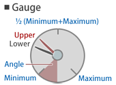
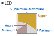
This defines the type of the pressure indicator. While both the gauge type and the LED type indicators can show two different pressures, this is not generally useful for the LED type as the upper LED shape will block the view into the lower LED shape.
The following spelling variations can be used:
Type, 形態
RedValue: The red component of the color. Measured from 0 (black) to 255 (red). The default value is 0.
GreenValue: The green component of the color. Measured from 0 (black) to 255 (green). The default value is 0.
BlueValue: The blue component of the color. Measured from 0 (black) to 255 (blue). The default value is 0.
▸ Options for Subject:
1 or BC or ブレーキシリンダ: Indicates the pressure of the brake cylinder.
2 or BP or ブレーキ管 or 制動管: Indicates the pressure of the brake pipe.
3 or ER or 釣り合い空気溜め or 釣り合い空気ダメ or つりあい空気溜め or ツリアイ空気ダメ: Indicates the pressure of the equalizing reservoir.
4 or MR or 元空気溜め or 元空気ダメ: Indicates the pressure of the main reservoir.
5 or SAP or 直通管: Indicates the pressure of the straight air pipe.
Creates the lower needle for a gauge-type pressure indicator, or defines the color of the lower shape for an LED-type indicator.
The following spelling variations can be used:
LowerNeedle, LowerHand, 下針
RedValue: The red component of the color. Measured from 0 (black) to 255 (red). The default value is 0.
GreenValue: The green component of the color. Measured from 0 (black) to 255 (green). The default value is 0.
BlueValue: The blue component of the color. Measured from 0 (black) to 255 (blue). The default value is 0.
▸ Options for Subject:
1 or BC or ブレーキシリンダ: Indicates the pressure of the brake cylinder.
2 or BP or ブレーキ管 or 制動管: Indicates the pressure of the brake pipe.
3 or ER or 釣り合い空気溜め or 釣り合い空気ダメ or つりあい空気溜め or ツリアイ空気ダメ: Indicates the pressure of the equalizing reservoir.
4 or MR or 元空気溜め or 元空気ダメ: Indicates the pressure of the main reservoir.
5 or SAP or 直通管: Indicates the pressure of the straight air pipe.
Creates the upper needle for a gauge-type pressure indicator, or defines the color of the upper shape for an LED-type indicator.
The following spelling variations can be used:
UpperNeedle, UpperHand, 上針
Y: The Y-coordinate in the panel image at which the center of the pressure indicator is placed in pixels. The default value is 0.
The following spelling variations can be used:
Center, 中心
For gauge-type indicators, defines the radius of the pressure gauge needle in pixels. For LED-type indicators, defines half the edge length of the LED-square in pixels. The radius is measured in pixels of the panel image.
The following spelling variations can be used:
Radius, 半径
Creates a background for the pressure indicator. The background is shown below the needles or the LED-square. Pure blue in the image (red=0, green=0, blue=255) represents transparent pixels.
The following spelling variations can be used:
Background, 背景
Creates a cover for the pressure indicator. The cover is shown on top of the needles or the LED-square. Pure blue in the image (red=0, green=0, blue=255) represents transparent pixels.
The following spelling variations can be used:
Cover, ふた
▸ Options for Value:
1 or kgf/cm2 or kgf/cm^2 or kg/cm2 or kg/cm^2: The unit is kilogram-force per centimeter squared (98066.5 Pa).
The following spelling variations can be used:
Unit, 単位
Defines the minimum pressure corresponding to the Angle measured clockwise from the 6 o’clock position. The default value is 0.
The following spelling variations can be used:
Minimum, 最小
Defines the maximum pressure corresponding to the Angle measured counter-clockwise from the 6 o’clock position. The default value is 1000.
The following spelling variations can be used:
Maximum, 最大
Defines the angle, measured clockwise from the 6 o’clock position, corresponding to the Minimum pressure, and also the angle, measured counter-clockwise from the 6 o’clock position, corresponding to the Maximum pressure. The default value is 45.
The following spelling variations can be used:
Angle, 角度
■ 6. The SpeedIndicator section
This section creates an analog speed indicator. You can use as many of these sections as required.
これをを定義することにより、セクションを開始します。
The following spelling variations can be used:
SpeedIndicator, Speedometer, 速度計
▸ Options for Value:
1: The pressure indicator is an LED.


The following spelling variations can be used:
Type, 形態
GreenValue: The green component of the color. Measured from 0 (black) to 255 (green). The default value is 255.
BlueValue: The blue component of the color. Measured from 0 (black) to 255 (blue). The default value is 255.
Defines the color for the needle (gauges) or for the overlay (LEDs).
The following spelling variations can be used:
Needle, Hand, 針
Y: The Y-coordinate in the panel image at which the center of the speed indicator is placed in pixels. The default value is 0.
The following spelling variations can be used:
Center, 中心
For gauge-type indicators, defines the radius of the pressure gauge needle in pixels. For LED-type indicators, defines half the edge length of the LED-square in pixels. The radius is measured in pixels of the panel image.
The following spelling variations can be used:
Radius, 半径
Creates a background for the pressure indicator. The background is shown below the needles or the LED-square. Pure blue in the image (red=0, green=0, blue=255) represents transparent pixels.
The following spelling variations can be used:
Background, 背景
Creates a cover for the pressure indicator. The cover is shown on top of the needles or the LED-square. Pure blue in the image (red=0, green=0, blue=255) represents transparent pixels.
The following spelling variations can be used:
Cover, ふた
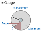
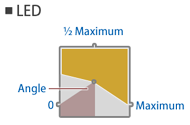
Defines the maximum speed corresponding to the Angle measured counter-clockwise from the 6 o’clock position. The default value is 120.
The following spelling variations can be used:
Maximum, 最大
Defines the angle, measured counter-clockwise from the 6 o’clock position, corresponding to the Maximum speed. The default value is 60.
The following spelling variations can be used:
Angle, 角度
Creates ATC indicators. The bitmap is required to have 13 square elements stacked horizontally, anchored at the right of the bitmap. The height of the bitmap defines the size of one square element. From left to right, the elements represent:

- 1st: ATC not currently available
- 2nd: 0 km/h speed restriction
- 3rd: 15 km/h speed restriction
- 4th: 25 km/h speed restriction
- 5th: 45 km/h speed restriction
- 6th: 55 km/h speed restriction
- 7th: 65 km/h speed restriction
- 8th: 75 km/h speed restriction
- 9th: 90 km/h speed restriction
- 10th: 100 km/h speed restriction
- 11th: 110 km/h speed restriction
- 12th: 120 km/h speed restriction
- 13th: ATS currently active
The center of any of the indicators is placed on a circle defined by Center as the center of the circle and AtsRadius as the radius of the circle. The angle at which an element is placed on that circle corresponds to the respective speed, or to the 6 o’clock position for the ATC not currently available and ATS currently active indicators. Only the one currently representative indicator is shown. Pure blue in the image (red=0, green=0, blue=255) represents transparent pixels.
The following spelling variations can be used:
AtcRadius, Atc半径
■ 7. The DigitalIndicator section
This section creates a digital speed indicator. You can use as many of these sections as required.
これをを定義することにより、セクションを開始します。
Creates a three-digit decimal speed display in kilometers per hour (km/h). The bitmap is required to have 11 elements stacked vertically, anchored at the top-right of the bitmap. From top to bottom, the 1st through 10th elements represent the digits 0 through 9, while the 11th element represents a missing digit that is shown in the 10s when the speed is below 10 km/h, and in the 100s when the speed is below 100 km/h. Pure blue in the image (red=0, green=0, blue=255) represents transparent pixels.
Top: The Y-coordinate in the panel image at which the top of the speed indicator is placed in pixels. The default value is 0.
Height: The height of a single digit inside the bitmap in pixels.
Defines the size of a single digit. Is required to be specified.
▸ Options for Value:
1 or mph: The unit is international miles per hour.
2 or m/s: The unit is meters per second.
■ 8. The PilotLamp section
This section creates a door indicator. You can use as many of these sections as required.
これをを定義することにより、セクションを開始します。
The following spelling variations can be used:
PilotLamp, 知らせ灯
The following spelling variations can be used:
TurnOn, 点灯
The following spelling variations can be used:
TurnOff, 消灯
Top: The Y-coordinate in the panel image in pixels at which the top of the pilot lamp is placed. The default value is 0.
The following spelling variations can be used:
Corner, 左上
■ 9. The Watch section
This section creates a watch consisting of needles for hour, minute and second. You can use as many of these sections as required.
これをを定義することにより、セクションを開始します。
The following spelling variations can be used:
Watch, 時計
Creates a background for the watch. The background is shown below the watch needles. Pure blue in the image (red=0, green=0, blue=255) represents transparent pixels.
The following spelling variations can be used:
Background, 背景
Y: The Y-coordinate in the panel image at which the center of the watch is placed in pixels. The default value is 0.
The following spelling variations can be used:
Center, 中心
The following spelling variations can be used:
Radius, 半径
GreenValue: The green component of the color. Measured from 0 (black) to 255 (green). The default value is 255.
BlueValue: The blue component of the color. Measured from 0 (black) to 255 (blue). The default value is 255.
Defines the color for all of the three needles (second, minute and hour).
The following spelling variations can be used:
Needle, Hand, 針
■ 10. The BrakeIndicator section
This section creates an indicator depicting the state of the power and brake handles. You can use as many of these sections as required.
これをを定義することにより、セクションを開始します。
Creates an indicator depicting the state of the power and brake handles. The bitmap is required to have a certain number of elements (depending on the train characteristics) stacked horizontally, anchored at the left of the bitmap. The height of the bitmap is equivalent to the height of an element. Pure blue in the image (red=0, green=0, blue=255) represents transparent pixels. The meaning of the elements depends on the type of brake systems used:
For air brakes, from left to right:
- Power notch n
- Power notch n-1
- …
- Power notch 2
- Power notch 1
- Release (REL)
- Lap (LAP)
- Service (SRV)
- Emergency brake (EMG)
For notched brakes without the hold brake device, from left to right:
- Power notch n
- Power notch n-1
- …
- Power notch 2
- Power notch 1
- Neutral
- Brake notch 1
- Brake notch 2
- …
- Brake notch m-1
- Brake notch m
- Emergency brake
For notched brakes with the hold brake device, from left to right:
- Power notch n
- Power notch n
- Power notch n-1
- …
- Power notch 2
- Power notch 1
- Neutral
- Hold brake
- Brake notch 1
- Brake notch 2
- …
- Brake notch m-1
- Brake notch m
- Emergency brake
Top: The Y-coordinate in the panel image at which the top of the indicator is placed in pixels. The default value is 0.
