■ 概要
- 1. 概要
- 2. Syntax
- 3. Preprocessing
- 4. The Options namespace
- 5. The Route namespace
- 6. The Train namespace
- 7. The Structure namespace
- 8. The Texture namespace
- 9. Cycle 名前空間
- 10. The Signal namespace
- 11. The Track namespace
■ 1. 概要
CSVルートは、テキストファイルに記述することで路線データを作成できます。
ファイルは任意のエンコードで記述されたプレーンテキストですが encoding、好ましい選択としてはバイトオーダー付きのUTF-8です。 parsing model に用いる数字は ルーズ(特に明記しない限りは)ですが、 それでも出力にあたっては 厳密な 出力をすることが望ましいです。 ファイルは任意のフォルダに格納できますが、カレントフォルダもしくは相対パスは Railway と Train フォルダ 以下に存在しなければなりません。 ファイル名は任意ですが、 拡張子は必ず .csv を用います。 ファイルは基本的に上から下に向かって解釈されていき、各行は式ごとに分割され、左から右に向かって解釈されていきます。
ルートファイルは、(Structure 名前空間)で定義された一連の命令セットにより、ルートデータ内で一貫して共通で利用されます 。 路線データ向けの追加のプロパティ、路線側が定義した既定の列車、沿線の背景のイメージファイルも同様に定義することができます。 最後に、ルートファイルは Track 名前空間でのコマンドにより指示します。 ここでは、 線路の座標 (殆どの場合、単位はメートル) を指定することにより、線路をカーブさせるタイミングや駅を設置したり、 壁や土手などを開始したり終わらせたりします。一般的には、 Track 名前空間はその他の名前空間を予め記述し、定義した後に記述する必要があります。
このフォーマットには、暗黙の規定として明示的に開始、または終了することが出来ない rail 0 があり、 それは路線の始端から終端まで常に存在します。 そしてそれはプレイヤーが走行するレールを示します。 rail 0 とその他の レールは 視覚的表示に用いられるだけでなく、 同様に Track Following Object にも用いられます。
幾何学的に、カーブや勾配は暗黙の rail 0 に対して作用しますが、 その他のすべてのレールは rail 0 に相対的に連動して定義され、 rail 0 のカーブや勾配に従って追従します。 オーバーライドされない限りファイルフォーマットではブロック長は25mの固定長で構築され、 特定のコマンドは25mのブロック単位でしか用いることができません。 オブジェクトの配置は、常に直線的に接続する非曲線座標系を想定しています。
➟ CSV ルートフォーマットのクイックリファレンスも参照して下さい…
■ 2. 文法
ファイルの各行の ホワイトスペース は、各行の行頭と行末では無視されます。 この時、各行はコンマ(U+002C)で区切られた個々の式に分割されます。 従って、各行は次のような形式をとります。
次に、其々の式は次の形式のいずれかをとります:
● コメント
コメントはパーサーによって完全に無視されます。 コメントを記述するには行頭をセミコロン (U+003B)で始める必要があります。
● 軌道の位置と長さ
負の数でない 厳密な 浮動小数点数で線路の距離程に対応します。 後続するすべてのコマンドは、Track名前空間からこの線路の距離程に関連付けられます。
これは、Options.UnitOfLengthと組み合わせて距離程の表現を用いるより複雑な方法です。 其々の パートi は 厳密な 浮動小数点数です。 パート1 は 係数1と乗算し, パート2 は 係数2など、 すべての要素に対して行われ、最終的な距離程をなします。 このパートは負でない数でなければなりません。 パートはコロン (U+003A)で分割されます。 要素の定義の詳細については Options.UnitOfLength を参照して下さい。
コマンド内において、長さを表す引数はどこにおいても、コロン表記で同様に記述することができます。 そのような場合は 緑 でハイライトされます。
n ユニットが Options.UnitOfLength を通じて定義されている場合でも、 いくつかのパラメータはコロン表記で記載されていても右側から結合されます。 つまり、左側のパラメータはスキップされます。 従って、 0:0:2、 0:2、 2 の表記は全て同様の意味を示します。
● コマンド
引数のないコマンド:
引数のあるコマンド:
コマンド名(引数1;引数2;引数3;…;引数n)
インデックスと引数を両方伴うコマンド:
コマンド名(インデックス1;インデックス2;…;インデックスm).サフックス 引数1;引数2;引数3;…;引数n
コマンド名(インデックス1;インデックス2;…;インデックスm).サフィックス(引数1;引数2;引数3;…;引数n)
ルール:
コマンド名 は大文字と小文字を区別しません。 インデックスと引数はセミコロン (U+003B)で分割されます。 コマンド名 とインデックス、引数の周囲にあるホワイトスペースは無視されます。 カッコに囲まれているホワイトスペースも同様に無視されます。
インデックスを用いた場合、 開きカッコ (U+0028) と閉じカッコ (U+0029)で囲まれている必要があります。 最低一つの引数、もしくは サフィックス がインデックスを用いる場合必須となります。
引数のエンコード方法は2種類のバリエーションがあります。 $-ディレクティブ ($Chr, $Rnd, $Sub, …)を除き、 自由にバリアントを選択できます。 バリアント 1: 最初の引数は、少なくともコマンドから一つのスペース (U+0020) で、コマンド、インデックスもしくは サフィックス で区切られます。 バリアント 2: 引数は、開き括弧 (U+0028) と閉じ括弧 (U+0029) に囲まれます。 後者の場合、 サフィックス は インデックスと接続して用いる場合には必須です。 括弧に囲まれる其々のホワイトスペースは無視されます。
一部のコマンドにおいて、 サフィックス は、引数のエンコードに用いるスタイルに関係なく必須であることに注意して下さい。 その場合 サフィックス は 太字 で記述され、 オプションの場合は 灰色 になります。
● With ステートメント
このステートメントの後、ピリオド (U+002E) で始まるすべてのコマンドは、 プレフィックスが付加されます。 例:
| ▶ |
With Route .Gauge 1435 .Timetable 1157_M |
上記の例は以下と同じ意味をなします:
| ▶ |
Route.Gauge 1435 Route.Timetable 1157_M |
■ 3. 前処理
ルートファイルのコマンドが実際に解釈される前には、 式は事前に処理されます。 最初に行われる処理は、 $-ディレクティブに対応する表現に置き換えます。 $Chr 、 $Rnd 、 $Sub ディレクティブは入れ子にすることができますが、 他方で $Include 、 $If 、 $Else 、 $EndIf は別のディレクティブにさらに入れ子にすることはできません。
$-ディレクティブの文法は自由には選べず、以下に示す形で従わなければなりません。
$Include(ファイルパス:距離程のオフセット)
$Include(ファイルパス1; 確率1; ファイルパス2; 確率2; …)
このディレクティブは、対応する確率に基づいて指定されたファイルからランダムに選択して、そのファイルの中身を指定されたメインファイルに含めます。 選ばれたファイルの中身は $Include ディレクティブの位置に差し替えられますので、それはすなわち例えば距離程と直前に使われたWithステートメントに注意を払わなければならないことを意味します。 引数処理において一番最後の確率が省略された場合、1として扱われます。
$Include ディレクティブは、大きなファイルを小さなファイルに分割したり、 共通のセクションのコードを複数のルートで共有したり、 大きなコードブロックからランダムに選択させたりするのに役立ちます。 インクルードされたファイルの中に更にファイルがインクルードされる場合がありますが、 それらが循環依存関係になっていないかどうかを確認し、注意する必要があります。 例えばファイル A が ファイル B をインクルードしている場合、 ファイル B がファイル A をインクルードしてしまっている場合などです。 (必要な場合を除き)インクルードファイルには.csvとは異なる拡張子を用いてユーザーが誤ってメインメニューから選択できないように考慮しておく必要があります。
ファイルi の後に :TrackPositionOffset が続く場合、 インクルードされるファイル内のすべての式は指定された距離程が メートル単位 でオフセットされます。 例えば、 $Include(stations.include:2000) は、part.includeがインクルードされる前に、ファイルに含まれるすべての距離程が2000メートル前方にシフトされます。 重要で理解しておかなければならないポイントとして、 “距離程” は$-ディレクティブが処理されるまでは実際に理解されないため、インクルードされるファイル内のすべての式は インクルードされた後実際の距離程に後にオフセットさせるためのフラグを内部的に立てるだけであることに注意して下さい。 即ちこれが意味する所として、インクルードされたファイル内に 1$Rnd(2;8)00 のような記述があったとして、まだ実際のオフセット後の距離程が形成されていない段階であっても、それらは正しくオフセットされます。
距離程のオフセット機能は release 1.2.11 以降に対応します。
このディレクティブは アスキーコード番号 で示される番号に対応するASCII 文字コードの文字へ置き換えます。 これは構文規則に用いる記号などを含めたりする場合や、除去したい場合に有用です。 関連するASCII文字のリスト:
| ASCIIコード番号 | 意味 | 文字 |
|---|---|---|
| 10 | 改行 | newline |
| 13 | 改行 | newline |
| 20 | スペース | space |
| 40 | 開き括弧 | ( |
| 41 | 閉じ括弧 | ) |
| 44 | カンマ | , |
| 59 | セミコロン | ; |
$Chr(13)$Chr(10) のシーケンスは単一の改行として扱われます。 $Chr(59) が挿入された場合、 それが使用されている場所に応じてコメントの開始、もしくは引数の区切り文字として解釈されます。
このディレクティブは 下限の数値 から 上限の数値 までのランダムな整数値を置き換えます。 これは例えば路線にランダム性を持たせたい時に有用です。
| Example for the use of the $Rnd directive: | |
| ▶ | 10$Rnd(3;5)0, Track.FreeObj 0; 1 |
| Possible outcome from the previous example is exactly one of these lines: | |
| ▶ |
1030, Track.FreeObj 0; 1 1040, Track.FreeObj 0; 1 1050, Track.FreeObj 0; 1 |
表現: 変数に格納される内容.
このディレクティブは単一の式としてのみ表示されます。 インデックス で割り当てられた場所へ、 表現 の内容で置き換えるために使用されます。 すべての割当が完了すると、 $Sub ディレクティブは空の文字列に置き換えられます。 $Rnd ディレクティブで生成された乱数値を変化させずに共用したい場合、それを保存したいときに有用です。 例については次の $Sub(インデックス) ディレクティブを参照して下さい。
実装にあたってのメモ
数値以外の文字列を格納することも可能ですが、 コンマを含める際に $Chr(44) を用いてもステートメントの区切りとして機能させることはできません。 ですが、 最初の文字として $Chr(59) 含めさせて、コメントとして機能させることは可能です。 条件式に用いる場合には、 $Include もしくは $If を用いる必要があります。
このディレクティブは、 変数インデックスに格納されている内容に置き換えます。 変数は置き換えられる前に予め設定されていなければなりません。
| Example for the use of the $Sub(Index)=Value and $Sub(Index) directives: | |
| ▶ |
$Sub(0) = $Rnd(3; 5) 1000, Track.FreeObj $Sub(0); 47 1020, Track.FreeObj $Sub(0); 47 1040, Track.FreeObj $Sub(0); 47 |
先の例では、3つ全ての Track.FreeObj コマンドにおいて、生成された乱数値は全て同じ数値が用いられ、FreeOBJのオブジェクトが同じレール上に配置されることが保証されます。 もし其々のFreeOBJの命令で其々 $Rnd(3;5) ディレクティブを指定した場合、 各オブジェクトはそれぞれ毎回、別のレール上に配置される可能性があります。
$If ディレクティブは、 状態が true (もしくは非ゼロの数値) と評価されたときのみ、後続の式を処理します。 $If の後に続く式の最後には、 $EndIf を記述しなければなりません。 オプションで、 $If と $EndIf の間に $Else ディレクティブを記述することができます。
$Else ディレクティブは、 それに先行して記述された $If ディレクションで false (ゼロ) と 評価されたときのみ、後に続く処理を処理できます。
$EndIf ディレクティブは、 その前に開始された $If ブロックの終了をマークするものです。
| Example of $If, $Else and $EndIf | |
| ▶ |
$Sub(1) = 0 With Track $If($Sub(1)) 1020, .FreeObj 0; 1 1040, .FreeObj 0; 2 $Else() 1030, .FreeObj 0; 3 $EndIf() |
| Another example of $If, $Else and $EndIf | |
| ▶ |
With Track 1050 $If($Rnd(0;1)), .FreeObj 0; 4, $Else(), .FreeObj 0; 5, $EndIf() |
$If ブロックは、入れ子処理をすることができます。 (最初の例のように)、もし $If/$Else/$EndIf をそれぞれ別の行に配置した場合、インデントを使用して可読性を改善させることができます。
最後に、 $-ディレクティブの全ての処理を終えると、 ルートファイルにある全ての表現は、それに関連する距離程に従って自動的にソートされます。
| Example of a partial route file: | |
| ▶ |
1000, Track.FreeObj 0; 23 1050, Track.RailType 0; 1 10$Rnd(3;7)0, Track.Rail 1; 4 Track.FreeObj 1; 42 |
| Preprocessing the $Rnd directive (assuming 3 is produced): | |
| ▶ |
1000, Track.FreeObj 0; 23 1050, Track.RailType 0; 1 1030, Track.Rail 1; 4 Track.FreeObj 1; 42 |
| Sorting by associated track positions: | |
| ▶ |
1000, Track.FreeObj 0; 23 1030, Track.Rail 1; 4 Track.FreeObj 1; 42 1050, Track.RailType 0; 1 |
■ 4. Options 名前空間
この名前空間におけるコマンドは、その他のコマンドの処理において路線ファイル全体に渡って影響を与えるオプションを提供します。 他の名前空間でコマンドを用いる前に、この名前区間のコマンドを予め実行しておく必要があります。
このコマンドを用いることで、他のコマンドで用いる長さの単位を指定できます。 汎用のユニット単位を Part1:Part2:…:Partn と入力すると、 其々の Parti は FactorInMetersi に準ずる距離程に乗算され、 そののち全ての実体の距離程をメートル単位で生成します。 理想は Options.BlockLength を使用して、ブロック長を使用する単位の整数倍に設定すべきです。
単位の変換例:
| 希望するユニットの単位 | 閑散係数 |
|---|---|
| mile | 1609.344 |
| chain | 20.1168 |
| meter | 1 |
| yard | 0.9144 |
| foot | 0.3048 |
以下においては、 Options.UnitOfLengthの影響を受ける時はいつも、全てのコマンドの全ての引数は 緑 にハイライトされます。
このコマンドは他のコマンドで使用する速度の単位をを指定して使用することが出来ます。閑散係数の例:
| 希望の単位 | 換算係数 |
|---|---|
| meters/second | 3.6 |
| miles/hour | 1.609344 |
| kilometers/hour | 1 |
以下においては、 Options.UnitOfLengthの影響を受ける時はいつも、全てのコマンドの全ての引数は 青 にハイライトされます。
このコマンドを用いることで、ブロック長を指定できます。 これは路線全体の設定であり、途中で変更をすることは出来ません。 Length は、 Options.UnitOfLength が Options.BlockLength より前で使用されている場合、 Options.UnitOfLength で指定された単位でのみ表されます。
▸ Mode で使用可能なオプション:
1: 線路ベース: カメラがオブジェクトの終わりを通過するとすぐに、オブジェクトは非表示になります。 これは線路の位置ベースで測定されます。 自己交差トラック (ループなど) は出来ません。
▸ Mode で使用可能なオプション:
1: Simplified: In Track.Section Aspect0; Aspect1; …; Aspectn, the section bears the smallest aspect which is higher than that of the following section.
▸ Mode で使用可能なオプション:
1: Signed: The CantInMillimeters parameter in Track.Curve is signed, i.e. negative values bank outward and positive ones inward on curved track. Cant can be applied on straight track, where negative values bank toward the left and positive ones toward the right.
▸ Mode で使用可能なオプション:
1: 補間: 霧の色と範囲は、隣接する Track.Fog コマンドの間で補間されます。 この動作は Track.Brightness を模倣しています。
▸ Mode で使用可能なオプション:
1: On: ファジー選択。. テクスチャが制限されたカラーパレットを使用している場合、透明色はパレットで最も近い使用可能な色に自動的に設定されます。
▸ Mode で使用可能なオプション:
1: On: ‘ハック’ を有効にします。
■ 5. Route 名前空間
この名前空間のコマンドは、路線の一般的なプロパティを定義します。
テキストに改行やコンマ等を含めたい場合は $Chr ディレクティブを使用する必要があります。
テキストに改行やコンマ等を含めたい場合は $Chr ディレクティブを使用する必要があります。
▸ Mode で使用可能なオプション:
0: 保安装置を 有効 にし、かつ 非常 ブレーキが適用されます。
1: 保安装置を 無効 にし、かつ 非常 ブレーキが適用されます。
Train.Gauge は Route.Gauge と同じ意味を持ちます。
Speed: 対応するアスペクトが許容する速度を定義する浮動小数点数。 デフォルト の単位は キロメートル毎時 (km/h) です。
このコマンドを使用して、速度制限を信号の現示「アスペクト」に関連付けます。 アスペクト 0 は赤信号を示し、 値が大きいほど速度の許容度が高いことを表します。デフォルトの値(日本の信号システム)は次のとおりです:
| インデックス番号 | アスペクト | 速度 |
|---|---|---|
| 0 | ● | 0 km/h |
| 1 | ●● | 25 km/h |
| 2 | ● | 55 km/h |
| 3 | ●● | 75 km/h |
| 4 | ● | 無制限 |
| 5 | ●● | 無制限 |
このコマンドは、一つ以上の運転する列車の前後の列車を生成します。此等の列車は路線に表示され、完全に機能し、運転する列車と同じ外観を使用します。 他の列車は運転する列車と同じ時刻表に従いますが、 Interval によって時間的にオフセットされます。 Track.Sta コマンドにより、運転する列車のみ、または前後を走る列車のみが停止する駅を定義することが出来ます。 後続の列車は配置されたセクションが他の列車によってクリアされた後にのみ表示されますが、運転する列車は現在の信号セクションの状態に関係なく設置されます。 従って、路線の開始時に運転する列車が表示されるセクションを前後の列車がクリアしていることを確認する必要があります。
Route.RunInterval は Train.Interval と同じ意味を持ちます。
このコマンドを使用すると、速度に関連するメッセージが表示された際(速度超過など)、カスタム速度単位、 mph等で表示することが出来ます。
このコマンドを使用すると、カスタム画像をロード画面の背景として使用することが出来ます。
このコマンドを使用すると、シミュレーションの開始時刻を設定することが出来ます。
この値が設定されていないか無効な場合、シミュレーションは始発駅に設定された到着時間に開始されます。
このコマンドは、 Route.AmbientLight 、 Route.DirectionalLight および Route.LightDirection コマンドの代わりとして使用できます。
これを用いることで、時間ベースのモデルを使用して照明を変化させることが出来ます。次のページで詳しく説明しています。
GreenValue: 環境光の緑の要素を表す0から255までの範囲の整数。 デフォルト値は 160 です。
BlueValue: 環境光の青の要素を表す0から255までの範囲の整数。 デフォルト値は 160 です。
このコマンドは、使用する環境光の色を定義します。 3D空間内の全てのポリゴンは、ライトの方向に関係なく、 環境光によって照らされます。
GreenValue: 指向性ライトの緑の要素を表す0から255までの範囲の整数。 デフォルト値は160です。
BlueValue: 指向性ライトの緑の要素を表す0から255までの範囲の整数。 デフォルト値は160です。
このコマンドは、使用する指向性ライトを定義します。 3D空間内のポリゴンは、ライトの方向が前面に差している場合にのみ、指向性ライトによって完全に照らされます。 背面に差している場合、指向性ライトは効果を与えません。 Route.LightDirection を設定して、光の方向を指定する必要があります。
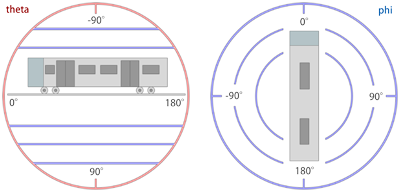
Phi: ライトの方向の回転の面の 度 の角度を表す浮動小数点数。 デフォルト値は -26.57 です。
このコマンドは、 自線の距離程0における初期の光の方向を定義します。 これは光が当たる方向で、 太陽が位置する方向とは反対の方向であることを意味します。 まず最初に、 Theta がピッチを決定します。 90 は下の方向を示し、 -90 は上方向を示します。 此等の値が極端な場合、 Phi の値は無関係になります。 Theta の値が0の時、後ろの水平線から始まる順方向を示します。 ピッチが Theta によって決定されると、 Phi が平面の回転を決定します。 値が0のときは回転せず、 90 の時は右方向に回転し、 -90 の時は左方向に回転します。 Theta と Phi を 180 と 0 、または 0 と 180 に設定することで、 逆方向を両方とも取得できます。 中間の値を取ることで、正確な光の方向をより正確に制御できます。
| Converting a spherical direction (theta,phi) into a cartesian direction (x,y,z): | |
| ƒ |
x = cos(theta) * sin(phi) y = -sin(theta) z = cos(theta) * cos(phi) |
| Converting a cartesian direction (x,y,z) into a spherical direction (theta,phi) for y2≠1: | |
| ƒ |
theta = -arctan(y/sqrt(x2+z2)) phi = arctan(z,x) |
| Converting a cartesian direction (x,y,z) into a spherical direction (theta,phi) for y2=1: | |
| ƒ |
theta = -y * pi/2 phi = 0 |
上記の数式では、 cos(x) はコサインを表し、 sin(x) は正弦、 arctan(x) は逆正接、 arctan(x,y) は2つの引数の逆正接、 sqrt(x) は平方根を表します。 どちらか一方を使用するほうが、もう一方を使用するよりも直感的に見える場合、数式を用いると、球座標とデカルト座標を変換することが出来ます。数式は、光の方向が数学的に定義される公式文書として機能します (ラジアンを三角関数として用いる場合)。
0 : The camera will be placed in the cab. (Default)
1 : The camera will be placed in ‘Exterior Camera’ mode.
2 : The camera will be placed in ‘Track Camera’ mode.
3 : The camera will be placed in ‘Flyby Camera’ mode.
4 : The camera will be placed in ‘Flyby Zooming Camera’ mode.
このコマンドを使用すると、路線作成者は初期カメラを代替のカメラモードの一つへ設定することが出来ます。
このコマンドはOpenBVEによって無視されます。
■ 6. Train 名前空間
この名前空間のコマンドは、路線と列車の関連付けを定義します。
Train.File FolderName
Train.Rail(RailTypeIndex).Set RunSoundIndex
列車の作成者は様々な走行音のレパートリーを提供します。 このコマンドを用いることで、それらの走行音を路線で使用するレールの種類に関連付けます。 どのレールでも正しい走行音を鳴らすには、列車の開発者と作業を調整する必要があります。詳細については standards に関するページをご覧下さい。
FlangeSoundIndex: A non-negative integer representing the train’s flange sound to associate to the rail type.
列車の開発者は様々なフランジ音を提供します。このコマンドを用いることで、此等のフランジ音を路線で使用するレールの種類に関連付けます。路線製作者が使用するレールの種類に対して正しいサウンドを再生させるためには、列車の開発者と協力して作業を調整する必要があります。 詳細については standards を参照して下さい。
FileName: 列車のフォルダを基準にした (1番目の 選択肢)、若しくは Object フォルダを基準にした (2番目の 選択肢)、昼間の時刻表のファイル名
このコマンドを使用して、時刻表の日中のバージョンをロードします。特定の駅から開始して表示する時刻表のインデックスは、Track.Staコマンドで設定できます。
FileName: 列車のフォルダを基準とした (1番目の 選択肢)、若しくは Object フォルダを基準とした (2番目の 選択肢)、夜間の時刻表のファイル名
このコマンドを使用して、時刻表の夜間のバージョンをロードします。特定の駅から開始して表示する時刻表のインデックスは、Track.Staコマンドで設定できます。
Train.Gauge は Route.Gauge と同じ意味を持ちます。
Train.Interval is the same as Route.RunInterval.
このコマンドは、先行列車が移動できる最高速度制限を定義します。実際の制限速度はTrack.Limitによって下げることが出来ます。運転する列車はこの設定の影響を受けず、Track.Limitで定義された制限まで移動する可能性があります。
このコマンドはOpenBVEでは無視されます。
このコマンドはOpenBVEでは無視されます。
■ 7. Structure 名前空間
Structure名前空間のコマンドは、他のコマンドで使用するオブジェクトを定義します。通常、Track.Rail、 Track.FreeObjなどのコマンドは、 StructureIndex によって参照されるオブジェクトを定義します。 この StructureIndex は、そのコマンドに固有であるため、 Track.Rail、Track.FreeObjなどに固有のオブジェクトのセットを定義できます。
Structure名前空間のコマンドの一般的な構文は次のとおりです。:
StructureIndex は負でない整数。 FileName は読み込ませるオブジェクトファイル名で Object フォルダと連携します。 Command は以下のコマンドになります:
| Command: | Remarks |
|---|---|
| Ground | Cycle.Ground 及び Track.Groundで用いるオブジェクトを定義します。 |
| Rail | Track.Rail、Track.RailStart 及び Track.RailType で用いるオブジェクトを定義します。 |
| WallL | Track.Wall の左側のオブジェクトを定義します。 |
| WallR | Track.Wall の右側のオブジェクトを定義します。 |
| DikeL | Track.Dike の左側のオブジェクトを定義します。 |
| DikeR | Track.Dike の右側のオブジェクトを定義します。 |
| FormL | Track.Form の左側の線路寄りのオブジェクトを定義します。 |
| FormR | Track.Form の右側の線路寄りのオブジェクトを定義します。 |
| FormCL | 変形可能なTrack.Formの左側を定義します。 アニメーテッドオブジェクトはサポートされていません。 |
| FormCR | 変形可能なTrack.Formの右側を定義します。 アニメーテッドオブジェクトはサポートされていません。 |
| RoofL | Track.Formの左側の線路寄りの屋根のオブジェクトを定義します。 |
| RoofR | Track.Formの右側の線路寄りの屋根のオブジェクトを定義します。 |
| RoofCL | 変形可能なTrack.Formの左側の屋根のオブジェクトを定義します。 アニメーテッドオブジェクトはサポートされていません。 |
| RoofCR | 変形可能なTrack.Formの右側の屋根のオブジェクトを定義します。 アニメーテッドオブジェクトはサポートされていません。 |
| CrackL | 変形可能なTrack.Crackの左側のオブジェクトを定義します。 アニメーテッドオブジェクトはサポートされていません。 |
| CrackR | 変形可能なTrack.Crackの右側のオブジェクトを定義します。 アニメーテッドオブジェクトはサポートされていません。 |
| FreeObj | Track.FreeObj を定義します。 |
| Beacon | Track.Beacon のオブジェクトを定義します。 |
| Weather | Defines objects for weather generated using Track.Rain and Track.Snow. |
| DynamicLight | ダイナミックライティングを定義します。 |
通常、サポートされているオブジェクトの種類は B3D、 CSV、X及びANIMATEDです。 しかし、FormCL、FormCR、RoofCL、RoofCR、CrackL及びCrackRについては B3D、CSV及びXのみ受けいれます。
➟ form、roof 及び crackについての詳細情報はこちらを参照して下さい…
付け加えると、少々異なる構文を持った Structure.Pole コマンドもあります:
PoleStructureIndex: ポールのストラクチャのインデックス番号を表す負でない整数。
FileName: Object フォルダからの相対パスの、読み込ませるファイル名。
FreeObjを除くすべてのオブジェクトはブロックの先頭に挿入されるため、z軸上で0から ブロック長 (デフォルトは25m) まで拡張する必要がある事に注意して下さい。 使用法の詳細については Track 名前空間の其々のコマンドを参照して下さい。
■ 8. Texture 名前空間
この名前空間のコマンドは使用する背景画像と、それらの配置方法を定義します。
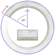
背景画像は、カメラの周囲の円柱状の壁として表示され、この壁の開始点 (上から見た場合) は最初の前方方向から60度 ( 10 時の方向)です。 そこから、背景画像は Texture.Background(BackgroundTextureIndex).X を用いて覆うように時計回りに円筒状に繰り返し、デフォルトでは真円の中に6回繰り返されます。
画像の上部4分の3は地平線の上に表示され、下部4分の1は地平線の下に表示されます。 Texture.Background(BackgroundTextureIndex).Aspectを通じて、 円柱の高さを固定するか、テクスチャのアスペクト比を維持するかを選択できます。 画像の高さが固定されている必要がある場合、円柱の高さは半径の2分の1になります。これは、画像の上部に対して約20度、画像の下部に対して約-7度の傾斜に相当します。もし画像のアスペクト比が維持されている場合、これには画像の幅と高さだけでなく、繰り返しの回数も考慮されます。
選択した繰り返しの回数に関係なく、テクスチャの左端と右端がシームレスにフィットする事を確認する必要があります。 また、画像の上部と下部の10%からサンプリングする上部と下部の蓋が作成されることも考慮に入れて下さい。 山の頂上のような極端なものが上部の蓋に入り込まないようにするため、画像の上部10%の中に入り込まないように注意する必要があります。
The image loaded into Texture.Background(0) is displayed at the beginning of the route, unless a Track.Back command at the beginning of the route requests a different image.
As an alternative Dynamic or Object based backgrounds may be used. The implementation of these is described upon this page:
This command loads a background image to be later used by Track.Back.
If a dynamic or object based background is to be used, this must instead point to the appropriate XML file.
Ignored if using a dynamic or object based background.
▸ Options for Mode:
1: Aspect: Preserve the aspect ratio of the image.
Ignored if using a dynamic or object based background.
■ 9. The Cycle namespace
GroundStructureIndexi: A non-negative integer indicating a ground structure that has been previously loaded via Structure.Ground.
When usually using Track.Ground(GroundStructureIndex), the same ground structure object will be repeatedly placed in every block. Via Cycle.Ground, you can override this behavior and automatically cycle through a series of different objects when using Track.Ground(GroundStructureIndex). The cycle repeats indefinitely, where GroundStructureIndex0 starts at track position 0. Technically, the i in GroundStructureIndexi chosen for a particular track position p is Mod[p / BlockLength, n].
RailStructureIndexi: A non-negative integer indicating a rail structure that has been previously loaded via Structure.Rail.
Consider the following definition:
| ▶ |
With Structure .Ground(0) grass.csv .Ground(1) river.csv .Ground(2) asphalt.csv |
The following two codes will produce the same output:
| ▶ |
With Track 0, .Ground 0 25, .Ground 1 50, .Ground 2 75, .Ground 0 100, .Ground 1 125, .Ground 2 ; and so on… |
| ▶ |
With Cycle .Ground(0) 0; 1; 2 With Track 0, .Ground 0 |
■ 10. The Signal namespace
Commands from this namespace define custom signals.
AnimatedObjectFile: A reference to an animated object file, relative to the Object folder.
Use this command to load signals directly from animated objects. The SignalIndex can be later referenced in Track.SigF commands to place the signal.
SignalFileWithoutExtension: A reference to a B3D/CSV/X object file representing the signal, relative to the Object folder, but without the file extension. Is required to be specified.
GlowFileWithoutExtension: An optional reference to a B3D/CSV/X object file representing the distance glow, relative to the Object folder, but without the file extension.
Use this command to load signals from a series of individual textures applied onto a common object. openBVE looks for X, CSV and B3D objects in this exact order. Textures are required to have the same name as the signal or glow, plus a non-negative aspect index, plus a file extension for textures. The SignalIndex can be later referenced in Track.SigF commands to place the signal.
For the SignalFileWithoutExtension, there should be the following files present (example):
SignalFileWithoutExtension.x
SignalFileWithoutExtension0.bmp
SignalFileWithoutExtension1.bmp
SignalFileWithoutExtension2.bmp
SignalFileWithoutExtensionn.bmp
The aspect indices from 0 through n represent successively more permissive aspects, where 0 is red. The built-in signals, for example, use the indices 0 (●), 1 (●●), 2 (●), 3 (●●), 4 (●) and 5 (●●). You can use as many as required.
All faces in the object will be applied the currently active aspect texture. This means that you cannot use any other texture in the object, but still have to assign texture coordinates appropriately. For the glow object, the above rules also apply. The glow object is usually a rectangle placed clearly in front of the signal, although you can also use different shapes.
The glow textures deserve special attention. All glow textures are pre-processed in the following way:
| A | B | C | D | E | F |
|---|---|---|---|---|---|
 |
 |
 |
 |
 |
 |
最初のテクスチャは、通常は楕円形のシャープな形状である必要があります。 形状は中心から完全に満たされ、外側の縁で真っ白に溶け込ませる必要があります。形状の周囲は完全な黒 (A) または完全な白 (B) の何れかです。
When openBVE loads the glow texture, it will replace all purely black pixels with purely white pixels, thus arriving at (B). From there, the image is inverted (C), then hue-shifted by 180 degrees (D). Compared to (B), this has the overall effect of inverting the lightness of the image, i.e. fully saturated pixels will be left unchanged (e.g. the core), while bright pixels (such as the outer rim of the shape) will become dark, and vice versa. Then, the image is gamma-corrected to further darken the dark parts (E), and finally, the image is blurred slightly (F).
The resulting texture is always additively blended. This means that instead of directly drawing the texture onto the screen, the pixels of the texture are added to the screen pixels. Here, adding black (0) does not change the screen pixels, while adding a fully satured color channel (1) will result in a fully satured color channel, e.g. adding white produces white. Keep in mind that when designing the textures, you will have to follow the inverse rules, e.g. design the image as depicted in (A) or (B), while having in mind how it will be processed afterward.
■ 11. Track 名前空間
Commands from this namespace define the track layout. Commands from this namespace should appear after commands from any of the other namespaces, and they usually form the largest part of the route file.
Use of track positions
All commands from the Track namespace need to be associated to track positions. Once a track position has been defined, all subsequent commands are associated to this track position until a new track position is defined. If you do not explicitly state a track position before the first command of the Track namespace is used, 0 will be assumed. While you do not need to use track positions in ascending order, series of commands which are associated the same track position will be sorted into ascending order once the file is loaded. While track positions can be any non-negative floating-point number, many commands in the Track namespace are only to be applied at the beginning of a block, which is 25m by default. For the default situation, this means that some commands are only to be used at track positions 0, 25, 50, 75, 100, 125 and so on. All commands for which this restriction applies are marked as such.
● 11.1. Rails
X: A floating-point number representing the horizontal distance from the player’s rail, by default measured in meters. Negative values indicate left, positive ones right.
Y: A floating-point number representing the vertical distance from the player’s rail, by default measured in meters. Negative values indicate below, positive ones above.
RailType: A non-negative integer referencing the rail type to use as defined by either a Structure.Rail or a Structure.Cycle command.
This command starts a new rail represented by the index RailIndex. Upon the point where this command is used, a rail of the same RailIndex must either not have been used so far in the route, or must have been ended via a Track.RailEnd command. If a rail of the same RailIndex was already used in the route, the default values of X, Y and RailType are the values last used by that rail, otherwise 0. If the rail is to be updated, use the Track.Rail command. If it is to be ended, use the Track.RailEnd command. You can end a rail of a given RailIndex and start a new rail of the same RailIndex at the same track position provided that the old rail is first ended and the new rail started afterward. For every block, a structure, determined by RailType, is automatically placed.
This command can only be used at the beginning of a block.
X: A floating-point number representing the horizontal distance from the player’s rail, by default measured in meters. Negative values indicate left, positive ones right.
Y: A floating-point number representing the vertical distance from the player’s rail, by default measured in meters. Negative values indicate below, positive ones above.
RailType: A non-negative integer referencing the rail type to use as defined by either a Structure.Rail or a Structure.Cycle command.
This command starts a new rail or updates an existing rail. The rail is represented by the index RailIndex. If a rail of the same RailIndex was already used in the route, the default values of X, Y and RailType are the values last used by that rail, otherwise 0. If the rail is to be ended, use the Track.RailEnd command. You can end a rail of a given RailIndex and start a new rail of the same RailIndex at the same track position provided that the old rail is first ended and the new rail started afterward. In each block, the X and Y values are repeated if a Track.Rail command is not used for that block. As a consequence, updating the X or Y values affects the layout of the rail from the preceding block only. Changing the RailType will affect the rail from the point on where this command is used. If this command is used multiple times on the same track position for the same rail, then the first instance of the command takes effect, while subsequent ones are ignored.
This command can only be used at the beginning of a block.
Using a RailIndex value of 0 is not valid for this command: Errata Note
Track.RailStart vs. Track.Rail
If you want to start a new rail, you can either use Track.RailStart or Track.Rail. When using Track.RailStart, you provide markup that a new rail is in fact to be started, which is invalid if the rail already exists. Using an explicit Track.RailStart will protect you from using a RailIndex which is already in use, in which case an error message is generated.
RailType: A non-negative integer referencing the rail type to use as defined by either a Structure.Rail or a Structure.Cycle command. The default value is 0.
This command changes the rail type for an existing rail, represented by RailIndex. The rail must have been started with a Track.RailStart or Track.Rail command and must not have been ended by a Track.RailEnd command. Changing the RailType will affect the rail from the point on where this command is used.
This command can only be used at the beginning of a block.
X: A floating-point number representing the horizontal distance from the player’s rail, by default measured in meters. Negative values indicate left, positive ones right.
Y: A floating-point number representing the vertical distance from the player’s rail, by default measured in meters. Negative values indicate below, positive ones above.
This command ends an existing rail, represented by the index RailIndex. The default values of X and Y are the ones last used by the rail. Once this command is used for a specific RailIndex, the corresponding rail is considered to be non-existing afterward.
This command can only be used at the beginning of a block.
Using a RailIndex value of 0 is not valid for this command: Errata Note
| Example of Track.RailStart, Track.Rail, Track.RailType and Track.RailEnd commands | |
| ▶ |
With Track 1000, .RailStart 1; 3.8; 0.0; 0 1025, .RailType 1; 1 1050, .Rail 1; 1.9; 0.0; 0 1075, .RailEnd 1 |
In the preceding example, rail 1 starts with an x-value of 3.8 and bears a rail index which corresponds to an object intended to depict a straight rail. The rail keeps the x-value of 3.8 at track position 1025, where the rail type is changed to correspond to an object intended to depict an s-shaped curve. At track position 1050, the rail is redefined to have an x-value of 1.9, after which the rail is straight again until 1075, where it is ended, still having an x-value of 1.9.
This command sets the accuracy of the track from this point on. Values should be in the range from 0 to 4, where 0 means perfect accuracy (no inaccuracy at all), 1 means very good accuracy (high speed lines), 2 means good accuracy, 3 means mediocre accuracy, and 4 means poor accuracy. Intermediate values are also possible. Currently, values below 0 are clamped at 0, and values above 4 are clamped at 4.
This command sets the adhesion of the track from this point on. As a reference, the value of 135 represents dry conditions, 85 represents frost and 50 represents snowy conditions. With a value of 0, the train will not be able to move at all.
WeatherType: A non-negative integer referencing the weather type to use as defined by Structure.Weather from this point onwards.
This command sets the intensity of the current rainfall, and the weather object to be shown.
It is also possible to set the rain intensity using the legacy BVE4 beacon based method. If these commands are present in the route, all Rain commands will be ignored.
WeatherType: A non-negative integer referencing the weather type to use as defined by Structure.Weather from this point onwards.
This command sets the intensity of the current snowfall, and the weather object to be shown.
Combining rain and snow
Rain and snow may be combined, and the simulation will show an appropriate random raindrop or snowflake on the windscreen, based upon the following probabilities:
The base probability for a drop / flake to appear is the greater of the rainfall and snowfall intensities.
The snowfall intensity is then used as the probability that this is a snowflake.
For example, with rainfall at 50 and snowfall at 40, there is a 50% chance for a drop to be added to the windscreen on each tick.
Of this, there is a 40% chance that this will be a snowflake.
● 11.2. Geometry
This command defines the pitch of all rails from this point on. Negative values indicate a downward gradient, positive ones an upward gradient. The value of 0 represents a level track. Rate can be calculated from a length difference X and a height difference Y in the following way:
| Rate expressed through X and Y: | |
| ƒ | Rate = 1000 * Y / X |
This command can only be used at the beginning of a block.
CantInMillimeters: A floating-point number which represents the superelevation of a banked curve, always measured in millimeters (0.001 meters). The default value is 0. See also Options.CantBehavior.
This command defines the radius of the curve for the player’s rail from this point on. Negative values for Radius indicate a curve to the left, positive ones to the right. The value of 0 represents straight track. The CantInMillimeters parameter defines the cant (superelevation) in millimeters. If Options.CantBehavior is 0 (default), only the absolute value of CantInMillimeters is considered, and the superelevation is always towards the curve center (inward). Also, cant cannot be applied on straight track. If Options.CantBehavior is 1, CantInMillimeters is signed, i.e. negative values bank outward and positive ones inward on curved track. Also, cant can be applied on straight track, where negative values bank toward the left and positive ones toward the right.
This command can only be used at the beginning of a block.
This command creates a point-based turn at the point of insertion. Ratio indicates the ratio between the length difference Z and the horizontal offset X in the following way:
| ƒ | Ratio = X / Z |
A negative ratio represents a turn to the left, a positive one to the right. The value of 0 represents a straight track.
This command can only be used at the beginning of a block.
This command is deprecated - use Track.Curve instead.
This command defines the height of the player’s rail above the ground at the point of insertion. It influences the placement of the ground objects defined via Structure.Ground and changed via Track.Ground. The height is interpolated between adjacent Track.Height commands. For example, the following two codes produce equivalent results:
| Example of a Track.Height command interpolated at 25m boundaries: | |
| ▶ |
1000, Track.Height 1 1075, Track.Height 4 |
| Example of Track.Height explicitly set each 25m to produce the same result: | |
| ▶ |
1000, Track.Height 1 1025, Track.Height 2 1050, Track.Height 3 1075, Track.Height 4 |
This command can only be used at the beginning of a block.
● 11.3. Objects
FreeObjStructureIndex: A non-negative integer representing the object to place as defined via Structure.FreeObj. The default value is 0.
X: The x-offset from the (straight) rail, by default measured in meters. Negative values represent the left, positive ones the right. The default value is 0.
Y: The y-offset from the (straight) rail, by default measured in meters. Negative values represent below the top of the rails, positive ones above. The default value is 0.
Yaw: The angle in degrees by which the object is rotated in the XZ-plane in clock-wise order when viewed from above. The default value is 0.
Pitch: The angle in degrees by which the object is rotated in the YZ-plane in clock-wise order when viewed from the left. The default value is 0.
Roll: The angle in degrees by which the object is rotated in the XY-plane in clock-wise order when viewed from behind. The default value is 0.
This places a “free” object a single time on a specified rail. The object must have been loaded via Structure.FreeObj(FreeObjStructureIndex) prior to using this command.
Direction: An integer indicating which wall to use as described below.
WallStructureIndex: A non-negative integer representing the object to place as defined via Structure.WallL and Structure.WallR. The default value is 0.
▸ Options for Direction:
0: Both the WallL and WallR objects are used.
1: The WallR object (right wall) is used.
This starts or updates a wall on a specified rail. The object must have been loaded via Structure.WallL(WallObjectIndex) or Structure.WallR(WallObjectIndex) prior to using this command. The walls are placed at the beginning of every block until a corresponding Track.WallEnd ends the wall for this rail. Please note that walls are resurrected if a rail is ended via Track.RailEnd and then started again via Track.RailStart or Track.Rail unless the wall was also ended via Track.WallEnd.
This command can only be used at the beginning of a block.
This ends an existing wall that was previously started via Track.Wall on a specified rail. The wall is not placed for the block in which this command is used.
This command can only be used at the beginning of a block.
Direction: An integer indicating which dike to use as described below.
DikeStructureIndex: A non-negative integer representing the object to place as defined via Structure.DikeL and Structure.DikeR. The default value is 0.
▸ Options for Direction:
0: Both the DikeL and DikeR objects are used.
1: The DikeR object (right dike) is used.
This starts or updates a dike on a specified rail. The object must have been loaded via Structure.DikeL(DikeObjectIndex) or Structure.DikeR(DikeObjectIndex) prior to using this command. The dikes are placed at the beginning of every block until a corresponding Track.DikeEnd ends the dike for this rail. Please note that dikes are resurrected if a rail is ended via Track.RailEnd and then started again via Track.RailStart or Track.Rail unless the dike was also ended via Track.DikeEnd.
This command can only be used at the beginning of a block.
This ends an existing dike that was previously started via Track.Dike on a specified rail. The dike is not placed for the block in which this command is used.
This command can only be used at the beginning of a block.
NumberOfAdditionalRails: A non-negative integer representing the amount of additional rails covered by this pole (i.e. this rail, plus NumberOfAdditionalRails rails). The default value is 0.
Location: If NumberOfAdditionalRails is 0, the side on which the pole is placed (see below), or the x-offset in multiples of 3.8 meters if NumberOfAdditionalRails is at least 1. The default value is 0.
Interval: An integer multiple of the block length specifying the interval in which poles are placed.
PoleStructureIndex: A non-negative integer representing the object to place as defined via Structure.Pole. The default value is 0.
This starts or updates a pole on a specified rail. The object must have been loaded via Structure.Pole(NumberOfAdditionalRails; PoleStructureIndex) prior to using this command. The poles are placed at the beginning of every block whose track positions are an integer multiple of the Interval (that is not necessarily at the same location this command is placed). If NumberOfAdditionalRails is 0, Locationindicates the side of the rail on which the pole is placed. If Location is less than or equal to 0, the pole is placed as-is (corresponding to the left side). If Location is greater than 0, the object is mirrored on the x-axis and then placed (corresponding to the right side). If NumberOfAdditionalRails is greater than or equal to 1, Location specifies the x-offset in multiples of 3.8 meters. Please note that poles are resurrected if a rail is ended via Track.RailEnd and then started again via Track.RailStart or Track.Rail unless the pole was also ended via Track.PoleEnd.
This command can only be used at the beginning of a block.
This ends an existing pole that was previously started via Track.Pole on a specified rail. The pole is not placed for the block in which this command is used.
This command can only be used at the beginning of a block.
This deforms a specified object to fill the space between two Rails.
RailIndex2: A non-negative integer representing the second RailIndex.
CrackStructureIndex: A non-negative integer representing the object defined in Structure.Crack
Note:
If RailIndex1 is to the left of RailIndex2 (e.g. it’s X-cordinate is smaller), then the object defined in Structure.CrackL will be used.
Otherwise, the objects defined in Structure.CrackR will be used.
This defines which ground objects to place from this point on. Ground objects are always placed at the beginning of a block at a certain height below the player’s rail (as defined via Track.Height). If no cycle was defined for CycleIndex, then the object loaded into Structure.Ground(CycleIndex) is placed. Otherwise, the cycle of ground objects as defined via Cycle.Ground(CycleIndex) is used.
This command can only be used at the beginning of a block.
● 11.4. Stations
ArrivalTime: The time the player’s train is expected to arrive at this station. Special values may also appear - see below.
DepartureTime: The time the player’s train is expected to depart from this station. Special values may also appear - see below.
PassAlarm: Indicates whether the pass alarm device should remind the driver of stopping at this station. The default value is 0.
Doors: Indicates which doors should open at this station. The default value is 0.
ForcedRedSignal: Indicates whether the signal behind the last station stop should be red on a train approach. The default value is 0.
System: Indicates which built-in safety system should apply until the next station. The default value is 0.
ArrivalSound: The sound file to be played on arrival, relative to the Sound folder.
StopDuration: A positive floating-point number indicating the minimum stop duration in seconds, including door opening/closing times. The default value is 15.
PassengerRatio: A non-negative floating-point number indicating the relative amount of passengers in the train from this station on. As a reference, 100 represents a train with normal amount of passengers, while 250 represents an over-crowded train. Values in-between 0 and 250 should be used. The default value is 100.
DepartureSound: The sound file to be played before departure (departure time minus sound duration minus door closing time), relative to the Sound folder.
TimetableIndex: A non-negative integer representing the timetable to be shown from this station on as defined via Train.Timetable(TimetableIndex).
▸ Available options for ArrivalTime:
omitted: The train may arrive at any time.
P or L: All trains are expected to pass this station.
B: The player’s train is expected to pass this station, while all other trains are expected to stop.
S: The player’s train is expected to stop at this station, while all other trains are expected to pass.
S:time: The player’s train is expected to arrive at this particular time, while all other trains are expected to pass.
D: This station is a dummy station for use in conjunction with ForcedRedSignal. No stop position overlay or timetable entry will be shown.
▸ Available options for DepartureTime:
omitted: The train may depart at any time.
T or =: This is the terminal station. If ForcedRedSignal is set to 1, the departure signal will be held at red indefinately.
T:time: This is the terminal station. If ForcedRedSignal is set to 1, the departure signal will still switch to green before the specified time as if this was a regular station.
C: This is a station at which to “change ends”. See the description below.
C:time: This is a station at which to “change ends”. Changing ends will take place at the specified time unless StopDuration interferes. See the description below.
J:index: This is a station at which the train is “jumped” to the station specified by index. See the description below.
J:index:Time: This is a station at which the train is “jumped” to the specified by index. Jumping will take place at the specified time unless StopDuration interfers. See the description below.
▸ Available options for PassAlarm:
1: The pass alarm device reminds the driver of stopping at this station.
▸ Available options for Doors:
N or 0: No doors are expected to open at this station, i.e. the train should simply come to a hold.
R or 1: The right doors are expected to open at this station.
B: Both the left and right doors are expected to open at this station.
▸ Available options for ForcedRedSignal:
1: The signal immediately following the last station stop is hold at red until the train reaches the stopping area and the departure time.
▸ Available options for System:
ATC or 1: ATC should be used from this station on. The following track is equipped with ATC.
このコマンドは、新しい駅を作成し、初期化します。 このコマンドは駅の一番進行方向手前に設置しなければなりません。 駅の作成を完了させるには、Track.Stopコマンドを使用し、このコマンドの後に停止位置目標を設置します。これ以降の全てのTrack.Stopコマンドは、この設置される駅に関連付けられます。 列車をこの駅に停車させる場合は、少なくとも一つ、Track.Stopを設置しなければなりません。
Special Features:
Stations can be marked as “changing ends” in the departure time. At such stations, when the departure time has been reached, the train will automatically jump to the next station. This feature is intended to fake a reverse of traveling direction without the need to jump to stations manually from the menu.
Similarly, stations can be marked as a “jump point” in the departure time. At such stations, when the departure time has been reached, the train will automatically jump to the specified station index.
The first occuring station in a route may not be of the Terminal type.
ArrivalTime: The time the player’s train is expected to arrive at this station. Special values may also appear - see below.
DepartureTime: The time the player’s train is expected to depart from this station. Special values may also appear - see below.
ForcedRedSignal: Indicates whether the signal behind the last station stop should be red on a train approach. The default value is 0.
System: Indicates which built-in safety system should apply until the next station. The default value is 0.
DepartureSound: The sound file to be played before departure (departure time minus sound duration minus door closing time), relative to the Sound folder.
▸ Available options for ArrivalTime:
omitted: The train may arrive at any time.
P or L: All trains are expected to pass this station.
B: The player’s train is expected to pass this station, while all other trains are expected to stop.
S: The player’s train is expected to stop at this station, while all other trains are expected to pass.
S:time: The player’s train is expected to arrive at this particular time, while all other trains are expected to pass.
▸ Available options for DepartureTime:
omitted: The train may depart at any time.
T or =: This is the terminal station. If ForcedRedSignal is set to 1, the departure signal will be held at red indefinately.
T:time: This is the terminal station. If ForcedRedSignal is set to 1, the departure signal will still switch to green before the specified time as if this was a regular station.
C: This is a station at which to “change ends”. See the description below.
C:time: This is a station at which to “change ends”. Changing ends will take place at the specified time unless StopDuration interferes. See the description below.
▸ Available options for ForcedRedSignal:
1: The signal immediately following the last station stop is hold at red until the train reaches the stopping area and the departure time.
▸ Available options for System:
ATC or 1: ATC should be used from this station on. The following track is equipped with ATC.
This command initializes a new station. Prefer using the Track.Sta command, which includes more options. For the options of Track.Sta which are not offered by Track.Station, the following values apply:
| PassAlarm | 0 (not used) |
|---|---|
| Doors | B (both doors must be opened) |
| ArrivalSound | Not played |
| StopDuration | 15 |
| PassengerRatio | 100 |
| TimetableIndex | Not affected |
コマンドは、駅のホームの先頭の位置に配置する必要があります。 駅の作成を完了させるには、Track.Stopコマンドを使用し、このコマンドの後に個別の両数の停止位置目標を設置する必要があります。 これ以降のTrack.Stopコマンドは、この設置された駅に関連付けられて個別の車両数に合わせた停止位置目標が設定されます。 列車をこの駅に停車させる場合は、少なくとも一つのTrack.Stopコマンドで停止位置目標を設置しなければなりません。
Stations can be marked as “changing ends” in the departure time. At such stations, when the departure time has been reached, the train will automatically jump to the next station. This feature is intended to fake a reverse of traveling direction without the need to jump to stations manually from the menu.
The first occuring station in a route may not be of the Terminal type.
BackwardTolerance: A positive floating-point number indicating the allowed tolerance in the backward direction, by default measured in meters. The default value is 5.
ForwardTolerance: A positive floating-point number indicating the allowed tolerance in the forward direction, by default measured in meters. The default value is 5.
Cars: A non-negative integer indicating for how many cars this stop point applies, or 0 for all cars. The default value is 0.
▸ Available options for Direction:
0: No stop post is created.
1: A stop post is created on the right side.
このコマンドは、作成された駅の停止位置目標を配置します。 もし駅に複数の車両の両数に合わせた個別の、または共通の停止位置目標を定義する場合、次のルールが適用されます:
- もし、編成の車両数が明確に設定されている場合は、その停止位置位置目標が使用されます。
- If an all cars stop is defined, this will be used.
- 車両数が一致する停止位置目標が設定されていない場合は、車両数が最も多く定義されている停止位置目標が使用されます。
- もし運転する車両数より多い両数に対応する停止位置目標が見つからなかった場合は、進行方向に向かって一番手前に設置された停止位置目標に停車します。
| Example of a station with multiple stop points: | |
| ▶ |
With Track 0100, .Sta STATION 0178, .Stop 1;;;4 ,; for 4 or less cars 0212, .Stop 1;;;6 ,; for 5 or 6 cars 0246, .Stop 1;;;8 ,; for 7 or 8 cars 0280, .Stop 1;;;0 ,; for 9 or more cars |
RailIndex2: The secondary RailIndex to which the platform will deform. Special values may also appear- see below.
RoofStructureIndex: A non-negative integer representing the object to be placed as defined via Structure.Roof
FormStructureIndex: A non-negative integer representing the object to be placed as defined via Structure.Form and Structure.FormC
▸ Available options for RailIndex2:
L: The specified FormL, FormCL and RoofL objects are placed without deformation.
R: The specified FormR, FormCR and RoofR objects are placed without deformation.
Note:
If RailIndex1 is to the left of RailIndex2 (e.g. it’s X-cordinate is smaller), then the objects defined in Structure.FormL, Structure.FormCL and Structure.RoofL will be used.
Otherwise, the objects defined in Structure.FormR, Structure.FormCL and Structure.RoofR will be used.
● 11.5. Signalling and speed limits
——
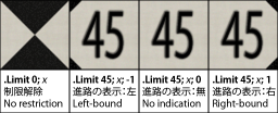
Post: The side on which to place a default Japanese-style speed limit post. The default value is 0.
Cource: The directional indication. The default value is 0.
▸ Options for Post:
0: No post will be placed.
1: The post is placed on the right side of the track.
▸ Options for Cource:
0: The post does not indicate a particular direction.
1: The post applies for a right-bound track.
This command defines the new speed limit from this point on. If the new speed limit is lower than the current speed limit, the new speed limit will take effect immediately. If the speed limit is higher than the current speed limit, the new speed limit will take effect only once the whole train has passed this point. By setting Speed to 0, the speed restriction is released. By setting Post to either -1 or 1, a default Japanese-style speed post is placed at the respective side of the track. Setting Course to either -1 or 1 includes a directional indication, which is usually used at railroad switches to indicate that the speed limit only applies if the respective direction is being taken. If Speed is set to 0, the setting of Course has no effect.
This command starts a section, the functional part of signalling, to be used in conjunction with Track.SigF, which creates a visual representation of a section (a signal). The ai parameters specify the aspects the section can bear. An aspect of 0 corresponds to a red section which must not be passed by a train. The a0 term is mandatory.
There are two different modes of behavior on how to interpret the ai parameters. The mode can be set via Options.SectionBehavior. The following are separate descriptions for default and simplified behavior.
Default behavior:
The ai terms specify the aspect the section should bear depending on how many sections ahead are clear until a red one is encountered. The order of the terms is relevant. The same aspect may occur multiple times.
▸ Meanings of the ai terms:
a1: The aspect to show when this section is clear, but the immediately following section is red.
a2: The aspect to show when this section and the following section are clear, but the one immediately following the latter one is red.
an: The aspect to show when n sections are clear before a red one is encountered.
In the case more sections ahead are clear than indicated by the ai terms, the section will bear the aspect of an.
Simplified behavior:
The ai terms specify the repertoire of aspects the section can have. A section will bear the smallest of the ai which is greater than the current aspect of the upcoming section. If no such ai exists, the section will bear the aspect of an. The order of the ai is irrelevant. If the same aspect occurs multiple times, this has no effect.
| Example of a Track.Section command in conjunction with a Track.SigF command: | |
| ▶ |
With Track 1000, .Section 0;2;4, .SigF 3;0;-3;-1 |
Section: A non-negative integer representing the section this signal is attached to, with 0 being the current section, 1 the upcoming section, 2 the section after that, and so on.
X: The X-coordinate to place the signal object, by default measured in meters. The default value is 0.
Y: The Y-coordinate to place the signal object, by default measured in meters. The default value is 0.
Yaw: The angle in degrees by which the object is rotated in the XZ-plane in clock-wise order when viewed from above. The default value is 0.
Pitch: The angle in degrees by which the object is rotated in the YZ-plane in clock-wise order when viewed from the left. The default value is 0.
Roll: The angle in degrees by which the object is rotated in the XY-plane in clock-wise order when viewed from behind. The default value is 0.
This command creates a non-function signal, that is, a visual representation of a section as defined via Track.Section. Setting Y to a negative number resets the y-coordinate to 4.8 meters and attaches a default signal post. Also see Track.Section.
If no object has been defined by Signal(SignalIndex), one of the default Japanese signals is used:
▸ Default signals for SignalIndex:
4: A four-aspect (type A) signal having aspects ●red, ●●yellow-yellow, ●yellow and ●green.
5: A five-aspect (type A) signal having aspects ●red, ●●yellow-yellow, ●yellow, ●●yellow-green and ●green.
6: A repeating signal equivalent to that created by Track.Relay.
Track.Sig Aspects; Unused; X; Y; Yaw; Pitch; Roll
Unused: This argument is not used by openBVE.
X: The X-coordinate to place the signal object, by default measured in meters. The default value is 0.
Y: The Y-coordinate to place the signal object, by default measured in meters. The default value is 0.
Yaw: The angle in degrees by which the object is rotated in the XZ-plane in clock-wise order when viewed from above. The default value is 0.
Pitch: The angle in degrees by which the object is rotated in the YZ-plane in clock-wise order when viewed from the left. The default value is 0.
Roll: The angle in degrees by which the object is rotated in the XY-plane in clock-wise order when viewed from behind. The default value is 0.
▸ Options for Type:
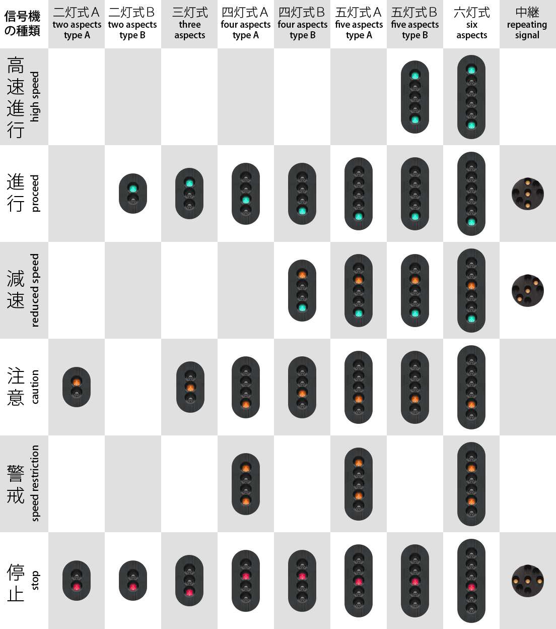
2: A two-aspect (type A) signal having aspects ●red and ●yellow.
-2: A two-aspect (type B) signal having aspects ●red and ●green.
3: A three-aspect signal having aspects ●red, ●yellow and ●green.
4: A four-aspect (type A) signal having aspects ●red, ●●yellow-yellow, ●yellow and ●green.
-4: A four-aspect (type B) signal having aspects ●red, ●yellow, ●●yellow-green and ●green.
5: A five-aspect (type A) signal having aspects ●red, ●●yellow-yellow, ●yellow, ●●yellow-green and ●green.
-5: A five-aspect (type B) signal having aspects ●red, ●yellow, ●●yellow-green, ●green and ●●green-green.
6: A six-aspect signal having aspects ●red, ●●yellow-yellow, ●yellow, ●●yellow-green, ●green and ●●green-green.
This command creates a functional signal. You can choose from the available options for Aspect to create any of the default Japanese signals. Setting X to 0 creates a functional but invisible signal similar to Track.Section. Setting X to a non-zero number and Y to a negative number resets the y-coordinate to 4.8 meters and attaches a default signal post.
| Example of a four-aspect type B signal without a post at x=-3 and y=5: | |
| ▶ | 1000, Track.Signal -4;;-3;5 |
| Example of a four-aspect type B signal including a post at x=-3 and y=4.8: | |
| ▶ | 1000, Track.Signal -4;;-3;-1 |
Track.Signal is similar to using Track.Section and Track.SigF in one command.
Y: The Y-coordinate at which to place the object, by default measured in meters. The default value is 0.
Yaw: The angle in degrees by which the object is rotated in the XZ-plane in clock-wise order when viewed from above. The default value is 0.
Pitch: The angle in degrees by which the object is rotated in the YZ-plane in clock-wise order when viewed from the left. The default value is 0.
Roll: The angle in degrees by which the object is rotated in the XY-plane in clock-wise order when viewed from behind. The default value is 0.
This commands creates a default Japanese repeating signal. The repeating signal repeats the state of the upcoming signal. Setting X to zero does not create a repeating signal, but forces the command to be ignored. Setting X to a non-zero number and Y to a negative number resets the y-coordinate to 4.8 and attaches a default signal post.
——
BeaconStructureIndex: A non-negative integer representing the object to be placed as defined via Structure.Beacon, or -1 to not place any object.
Section: An integer representing the section to which the beacon is attached, namely 0 for the current section, 1 for the upcoming section, 2 for the section behind that, etc., or -1 for the next red section.
Data: An integer representing arbitrary data specific to the beacon type to be transmitted to the train.
X: The X-coordinate at which to place the object, by default measured in meters. The default value is 0.
Y: The Y-coordinate at which to place the object, by default measured in meters. The default value is 0.
Yaw: The angle in degrees by which the object is rotated in the XZ-plane in clock-wise order when viewed from above. The default value is 0.
Pitch: The angle in degrees by which the object is rotated in the YZ-plane in clock-wise order when viewed from the left. The default value is 0.
Roll: The angle in degrees by which the object is rotated in the XY-plane in clock-wise order when viewed from behind. The default value is 0.
This command places a beacon (transponder). The object must have been loaded via Structure.Beacon(BeaconStructureIndex) prior to using this command. When the train passes the beacon, the type of beacon and various data will be transmitted to the train, including the state of the referenced section.
It should be noted that the built-in safety systems also receive data from these beacons as Track.Beacon(Type) is roughly equivalent to Track.Transponder(Type). Please see the page about beacon standards for more information.
Track.Tr Type; Signal; SwitchSystem; X; Y; Yaw; Pitch; Roll
Signal: The signal this transponder references. The default value is 0.
SwitchSystem: Whether to automatically switch the safety system. The default value is 0.
X: The X-coordinate at which to place the object, by default measured in meters. The default value is 0.
Y: The Y-coordinate at which to place the object, by default measured in meters. The default value is 0.
Yaw: The angle in degrees by which the object is rotated in the XZ-plane in clock-wise order when viewed from above. The default value is 0.
Pitch: The angle in degrees by which the object is rotated in the YZ-plane in clock-wise order when viewed from the left. The default value is 0.
Roll: The angle in degrees by which the object is rotated in the XY-plane in clock-wise order when viewed from behind. The default value is 0.
▸ Options for Type:
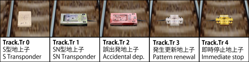
0: An S-type transponder used by ATS-S. Usually placed 600m in front of a signal.
1: An SN-type transponder used by ATS-SN. Usually placed 20m in front of a signal.
2: An accidental departure transponder. Usually placed shortly behind a station stop.
3: An ATS-P pattern renewal transponder. Usually placed 600m, 280m, 180m, 130m, 85m or 50m in front of a signal, depending on the circumstances.
4: An ATS-P immediate stop transponder. Usually placed either 25m or 30m in front of a signal, depending on the circumstances.
▸ Options for Signal:
1: The signal immediately behind the upcoming signal is referenced.
n: The n‘th signal behind the upcoming signal is referenced.
▸ Options for SwitchSystem:
0: The transponder automatically switches the train to ATS-SN for transponder types 0 and 1, and to ATS-P for types 3 and 4.
This command places a transponder, usually for the built-in safety systems ATS-SN or ATS-P. For more information about these systems and their transponders, see the user’s documentation about ATS.
It should be noted that custom safety system plugins also receive data from these transponders as Track.Transponder(Type) is roughly equivalent to Track.Beacon(Type). Please see the page about beacon standards for more information.
➟ Go here to find out more about ATS-SN and ATS-P.
This command places an S-type transponder for the built-in safety system ATS-SN, referencing the upcoming signal, and automatically switching to ATS-SN. The command is equivalent to Track.Tr 0;0;0. See there for more information.
This command places a pattern renewal transponder for the built-in safety system ATS-P, referencing the upcoming signal, and automatically switching to ATS-P. The command is equivalent to Track.Tr 3;0;0. See there for more information.
Speed: A non-negative floating-point number representing the speed restriction, by default measured in km/h.
▸ Options for Type:
1: A permanent speed restriction.
This command defines a speed restriction for the built-in safety system ATS-P.
A temporary speed restriction (Type=0) is to be inserted at the point where the speed restriction should apply. ATS-P will know about this speed restriction in advance and will brake the train so that the train meets the speed restriction at that point. Once the point is passed, the speed restriction no longer applies.
A permanent speed restriction (Type=1) is to be inserted at the point where the speed restriction should apply, however, ATS-P does not know about this limit in advance and will only brake the train from that point on. For a higher degree of realism, insert permanent speed restrictions at the same point as ATS-P transponders. A permanent speed restriction, as the name suggests, is remembered by ATS-P and is only released by a subsequent permanent speed restriction.
This command is equivalent to Track.Pattern 1;Speed. See there for more information.
——
This command defines which background image to show from now on.
This command can only be used at the beginning of a block.
EndingDistance: A floating-point number indicating the end of fog, by default measured in meters. The default value is 0.
RedValue: An integer ranging from 0 to 255 representing the red component of the fog. The default value is 128.
GreenValue: An integer ranging from 0 to 255 representing the green component of the fog. The default value is 128.
BlueValue: An integer ranging from 0 to 255 representing the blue component of the fog. The default value is 128.
This command defines the fog from this point on, or deactivates fog. If fog is to be enabled, StartingDistance must be less than EndingDistance. If fog is to be disabled, StartingDistance must be greater than or equal to EndingDistance.
Fog affects the coloring of objects. Objects before the starting distance appear as-is, objects after the ending distance appear in the fog color, and objects in-between blend linearly between those. The background image is affected by fog as well. For the fog calculations, the background image is assumed to be at 600 meters distance from the camera, regardless of the actual viewing distance.
Depending on Options.FogBehavior, there are two options how this command affects fog from this point on. In block-wise mode, the current fog blends from the beginning of this block to the new settings at the end of this block. The new setting is kept for following blocks. This is the default behavior. In interpolation mode, each Track.Fog command defines a control point for fog, where all of the settings (distances and colors) are interpolated linearly between the control points.
This command can only be used at the beginning of a block.
This command marks a point which affects the brightness in the cab. Value is measured from 0 (dark) to 255 (light), and is linearly interpolated between successive Track.Brightness commands for any given point on the track. This command should be used for tunnels, bridges, station roofs, or anything else that would affect the brightness as perceived inside the cab.
| Example: | |
| ▶ |
With Track 1200, .Brightness 255 ,; before the bridge starts 1205, .Brightness 128 ,; directly under the bridge here 1210, .Brightness 255 ,; as soon as the bridge ends |
Distance: A non-zero floating-point number indicating the length for which the marker image is displayed, by default measured in meters.
▸ Behavior for Distance:
positive value: The marker image starts to display Distance meters before the Track.Marker command, and ends at the Track.Marker command.
This command shows a so-called marker image, which is displayed in the top-right corner of the screen. You can use these images for advisory or informational purposes. The RGB color of 64,64,64 inside the image is made transparent.
A Track.Marker command, linking to a single XML file is also supported. These allow more control over markers than is available in the routefile commands.
These are fully described on the the XML Markers page…
Distance: A non-zero floating-point number indicating the length for which the text is displayed, by default measured in meters.
FontColor: The font color for this marker text
▸ Behavior for Distance:
positive value: The marker image starts to display Distance meters before the Track.Marker command, and ends at the Track.Marker command.
▸ Available options for FontColor:
2: Gray.
3: White.
4: Red.
5: Orange.
6: Green.
7: Blue.
8: Magenta.
This command creates a simple textual marker, which is added to the list of messages in the upper left-hand corner of the screen.
Track.POI RailIndex; X; Y; Yaw; Pitch; Roll; Text
X: A floating-point number representing the horizontal offset from the rail, by default measured in meters. Negative values indicate left, positive ones right.
Y: A floating-point number representing the vertical offset from the rail, by default measured in meters. Negative values indicate below, positive ones above.
Yaw: The angle in degrees by which the view is rotated in the XZ-plane in clock-wise order when viewed from above. The default value is 0.
Pitch: The angle in degrees by which the view is rotated in the YZ-plane in clock-wise order when viewed from the left. The default value is 0.
Roll: The angle in degrees by which the view is rotated in the XY-plane in clock-wise order when viewed from behind. The default value is 0.
Text: A textual representation of the point of interest.
This command creates a point of interest which the user can jump to by pressing the CAMERA_POI_PREVIOUS (NUM 1) or CAMERA_POI_NEXT (NUM 7) keys. The camera will be placed at the specified location with the specified orientation. If Text is non-empty, a message will appear briefly showing the text.
This commands creates a position-time-association for an invisible preceding train in order to influence signalling. Contrary to a real preceding train as created by Route.RunInterval, the invisible preceding train created by Track.PreTrain is a way of scripting where the invisible preceding train is at any given time. The position-time-associations must be in increasing order, that is, at a later track position, the associated time must also be later. Before the first scripted time, the invisible preceding train resides at the first scripted position. In-between the first and last scripted time, the invisible preceding train moves (linearly) between the scripted points. After the last scripted time, the invisible preceding train is removed and thus clears signalling.
Speed: The reference speed in km/h for speed-dependant sounds, or 0 to play the sound speed-independently. The default value is 0.
This command plays an announcement or other kind of sound in the cab once the player’s train crosses the point where this command is used. If Speed is set to 0 (default), the sound is played as-is. If a Speed is given though, the sound plays at is original pitch at the specified speed, and is pitch-modulated proportionally for other speeds, useful for custom flange sounds, pointwork sounds, etc.
X: A floating-point number representing the horizontal offset from rail 0, by default measured in meters. Negative values indicate left, positive ones right.
Y: A floating-point number representing the vertical offset from rail 0, by default measured in meters. Negative values indicate below, positive ones above.
This command places an environmental sound effect at the specified location. The sound will play in a loop for the duration of the simulation and employs the doppler effect. (Note: All sounds in openBVE employ the doppler effect.)
This command places a bumper. The train can collide with the bumper in both the forward and backward directions. Place this command at the beginning and the end of the route. An object is not automatically created, so use Track.FreeObj to create a visual representation of the bumper if necessary.
BeaconStructureIndex: A non-negative integer representing the object to be placed as defined via Structure.Beacon, or -1 to not place any object.
NextDestination: An integer representing the destination value set when passing over this beacon in a forwards direction, or -1 to disable.
PreviousDestination: An integer representing the destination value set when passing over this beacon in a reverse direction, or -1 to disable.
TriggerOnce: If set to 0, this beacon will be triggered by all valid trains which pass over it. If set to 1, it will be triggered by the first valid train only.
X: The X-coordinate at which to place the object, by default measured in meters. The default value is 0.
Y: The Y-coordinate at which to place the object, by default measured in meters. The default value is 0.
Yaw: The angle in degrees by which the object is rotated in the XZ-plane in clock-wise order when viewed from above. The default value is 0.
Pitch: The angle in degrees by which the object is rotated in the YZ-plane in clock-wise order when viewed from the left. The default value is 0.
Roll: The angle in degrees by which the object is rotated in the XY-plane in clock-wise order when viewed from behind. The default value is 0.
This command places a special beacon, which sets the destination variable, available for use by plugins and animated objects. The object must have been loaded via Structure.Beacon(BeaconStructureIndex) prior to using this command.
BeaconStructureIndex: A non-negative integer representing the object to be placed as defined via Structure.Beacon, or -1 to not place any object.
TriggerOnce: If set to 0, this beacon will be triggered by all valid trains which pass over it. If set to 1, it will be triggered by the first valid train only.
X: The X-coordinate at which to place the object, by default measured in meters. The default value is 0.
Y: The Y-coordinate at which to place the object, by default measured in meters. The default value is 0.
Yaw: The angle in degrees by which the object is rotated in the XZ-plane in clock-wise order when viewed from above. The default value is 0.
Pitch: The angle in degrees by which the object is rotated in the YZ-plane in clock-wise order when viewed from the left. The default value is 0.
Roll: The angle in degrees by which the object is rotated in the XY-plane in clock-wise order when viewed from behind. The default value is 0.
This command places a special beacon, which commands an AI driver to play the horn. Both an AI controlled player train and pure AI trains will trigger this beacon, unless TriggerOnce is set. The object must have been loaded via Structure.Beacon(BeaconStructureIndex) prior to using this command.
このコマンドは、 Route.AmbientLight 、 Route.DirectionalLight および Route.LightDirection コマンドの代わりとして使用できます。
これを用いることで、時間ベースのモデルを使用して照明を変化させることが出来ます。次のページで詳しく説明しています。
GreenValue: 環境光の緑の要素を表す0から255までの範囲の整数。 デフォルト値は 160 です。
BlueValue: 環境光の青の要素を表す0から255までの範囲の整数。 デフォルト値は 160 です。
This command defines the ambient light color to be used from this point onwards. All polygons in the scene are illuminated by the ambient light regardless of the light direction.
GreenValue: 指向性ライトの緑の要素を表す0から255までの範囲の整数。 デフォルト値は160です。
BlueValue: 指向性ライトの緑の要素を表す0から255までの範囲の整数。 デフォルト値は160です。
This command defines the directional light to be used from this point onwards. The polygons in the scene are only fully illuminated by the directional light if the light direction points at the front faces. If pointing at back faces, no light is contributed. Route.LightDirection should be set to specify the light direction.
Phi: ライトの方向の回転の面の 度 の角度を表す浮動小数点数。 デフォルト値は -26.57 です。
This command defines the light direction from this point onwards. This is the direction the light shines at, meaning the opposite direction the sun is located at. First, Theta determines the pitch. A value of 90 represents a downward direction, while a value of -90 represents an upward direction. With those extremes, the value of Phi is irrelevant. A value of 0 for Theta represents a forward direction originating at the horizon behind. Once the pitch is defined by Theta, Phi determines the rotation in the plane. A value of 0 does not rotate, a value of 90 rotates the direction to the right and a value of -90 rotates to the left. A backward direction can be both obtained by setting Theta and Phi to 180 and 0 or to 0 and 180, respectively. Values in-between allow for more precise control of the exact light direction.
The direction of the light is relative to the initial direction at the zero-point of the route (e.g Track position 0), not the current position.
| Converting a spherical direction (theta,phi) into a cartesian direction (x,y,z): | |
| ƒ |
x = cos(theta) * sin(phi) y = -sin(theta) z = cos(theta) * cos(phi) |
| Converting a cartesian direction (x,y,z) into a spherical direction (theta,phi) for y2≠1: | |
| ƒ |
theta = -arctan(y/sqrt(x2+z2)) phi = arctan(z,x) |
| Converting a cartesian direction (x,y,z) into a spherical direction (theta,phi) for y2=1: | |
| ƒ |
theta = -y * pi/2 phi = 0 |
上記の数式では、 cos(x) はコサインを表し、 sin(x) は正弦、 arctan(x) は逆正接、 arctan(x,y) は2つの引数の逆正接、 sqrt(x) は平方根を表します。 どちらか一方を使用するほうが、もう一方を使用するよりも直感的に見える場合、数式を用いると、球座標とデカルト座標を変換することが出来ます。数式は、光の方向が数学的に定義される公式文書として機能します (ラジアンを三角関数として用いる場合)。