■ 目錄
■ 1. 總概
一个B3D文件允许使用纯文本命令来创造单个物件。该物件可以在线路或车辆中使用。文件所描述的物件可以包含任意数量的多边形。B3D格式允许在[MeshBuilder]部分中对多个多边形进行分组,并将颜色或纹理信息等属性分配给在每个部分中创建的多边形。这允许在同一个[MeshBuilder]当中创建多个多边形,这些多边形共享同一属性。多边形在这里称为面。
该文件是以任意编码编码的纯文本文件,但是,带字节顺序标记的UTF-8是更好的选择。数字的解析方式 是 宽松的 ,尽管如此,编写时建议您必须写一些 严格正确的 数字。文件名是任意的,但必须有扩展名 .b3d 。该文件将从上到下逐行进行解析。
■ 2. 句法
文件中的每一行都分为命令名称及其参数。所有命令的语法都是相同的:
命令名称 不区分大小写。如果有参数,则 命令名称 和 参数1 需使用至少一个空格(U+0020)来分隔。参数用逗号(U+002C)分隔。参数周围及行的开头与结尾的 空格 都会被忽略。仅由空格组成的行或空行也被忽略。
在 参数i 处留空,也可以省略该参数。在省略时会应用特定的默认值。所有默认值都在下方有列出。
您可以在一行的末尾添加注释。注释由分号(U+003B,英文半角)开始。所有注释在开始解析文件之前就将被自动排除。
■ 3. 可用指令
这个命令标志着新一组面的开始。它必须位于以下任何命令之前。在文件中可以根据需要添加任意数量的该指令。后续的所有命令将与前一个[MeshBuilder]关联。
vY :顶点的y坐标,以米为单位,负值向下,正值向上,默认值为0。
vZ :顶点的z坐标,以米为单位,负值向后,正值向前,默认值为0。
nX :顶点法线的x坐标,默认值为0。
nY :顶点法线的y坐标,默认值为0。
nZ :顶点法线的z坐标,默认值为0。
这个命令将创建一个新顶点,然后可以将此顶点用于Face或Face2命令来创建面。在[MeshBuilder]部分中可以根据需要添加任意数量的该指令。但是,给出顶点的顺序对后续的命令很重要。给定的第一个顶点具有索引编号0,后续顶点具有索引1,2,3等等。
法线是在特定点垂直于面的方向。如果面里的所有顶点具有相同的法线,那么面将看起来平坦。如果使用得当,您可以通过为每个顶点指定不同的法线来造成曲面的错觉 - 跨多个面在所有顶点上使用相同法线除外。 请尽量使用简单的面和复杂的法线而不是复杂的面来达成曲面或凹凸效果。这能节省性能开支。 如果全部为0或不给出,法线将被自动计算。
This command creates a face given an arbitrary long list of vertex indices. The index corresponds to the order in which the vertices have been created by the Vertex command, thus the Face command needs to be stated after the corresponding Vertex commands. The first Vertex command used creates index 0, and subsequent Vertex commands create indices 1, 2, 3 and so on. The order in which the vertex indices appear is important. They need to be given in clockwise order when looking at the front of the face. The back of the face will not be visible. However, the Face2 command can be used to create a face which is visible from both sides. Only convex polygons are supported.
此命令将创建一个以所有给出v点为顶点的面。i的值(索引值)对应于AddVertex中创建顶点的顺序,因此该命令须在AddVertex命令之后使用。顶点索引出现的顺序很重要,必须以从面的正面来看的顺时针顺序给出。在相邻位置出现的顶点的连线不可以是该多边形的对角线。 仅支持凸多边形,凹多边形需要被拆成多个凸多边形。面的两边都可见,但在目前的openBVE版本里背面的光照计算会有错误。
HalfHeight: A floating-point number representing half the height of the cube in meters.
HalfDepth: A floating-point number representing half the depth of the cube in meters.
此命令将以原点(0,0,0)为中心创建一个以 两倍的半宽 , 两倍的半高 和 两倍的半深 为尺寸的立方体。即,在X轴上它占据 -半宽 到 半宽 的范围,在Y轴上它占据 -半高 到 半高 的范围,在Z轴上它占据 -半深 到 半深 的范围。立方体总有8个顶点和6个面。
立方体指令表示
The Cube command is equivalent to a series of Vertex and Face commands, which you need to account for when using other commands in the same [MeshBuilder] section. The details on what the Cube command does are available here.
UpperRadius: A floating-point number representing the radius for the upper base of the frustum in meters. Can be negative to indicate that the top cap is to be omitted.
LowerRadius: A floating-point number representing the radius for the lower base of the frustum in meters. Can be negative to indicate that the bottom cap is to be omitted.
Height: A floating-point number representing the height of the prism in meters. Can be negative, which will flip the frustum vertically and display it inside-out.
This command creates a frustrum. If LowerRadius and UpperRadius are equal, the object generated will reduce to a prism, which can be used as an approximation to the cylinder. If either LowerRadius or UpperRadius are zero, the object generated will reduce to a pyramid. The frustum will be centered on the origin (0,0,0). On the x- and z-axes, the frustum extends from -LowerRadius to LowerRadius for the lower base and from -UpperRadius to UpperRadius for the upper base. On the y-axis, the frustum extends from -1⁄2*Height to 1⁄2*Height.
当半径的值较小时, 如线杆或扶手,顶点数 n 为6或8就足够了。无论 上底半径 , 下底半径 和 n 的值如何,该多面体将始终有 2*n 个顶点和 n +2个面,除非省略上下底面。若 上底半径 或 下底半径 为负数,则采用其绝对值,同时不创建相应的底面(没有盖儿)。若 高 为负数,则上下底面会倒转(上底在下,下底在上),同时所有面都会变为内部可见(默认情况是外部可见) 。
截锥体命令表示
The Cylinder command is equivalent to a series of Vertex and Face commands, which you need to account for when using other commands in the same [MeshBuilder] section. The details on what the Cylinder command does are available here.
這個命令是會被OpenBVE忽略
TranslateAll X, Y, Z
Y: A floating-point number representing the translation on the y-coordinate in meters. Negative values translate down, positive ones up. The default value is 0.
Z: A floating-point number representing the translation on the z-coordinate in meters. Negative values translate backward, positive ones forward. The default value is 0.
The Translate command moves all vertices that have been created so far in the [MeshBuilder] section via the Vertex, Cube or Cylinder commands. Subsequent vertices are not affected. You can use as many Translate commands as desired in a [MeshBuilder] section. The TranslateAll command not only affects the vertices generated in the current [MeshBuilder] section, but also those created in previous [MeshBuilder] sections. This is useful to insert at the end of the file in order to translate the whole object.
ScaleAll X, Y, Z
Y: A non-zero floating-point number representing the scale factor on the y-coordinate. The default value is 1.
Z: non-zero A floating-point number representing the scale factor on the z-coordinate. The default value is 1.
The Scale command scales all vertices that have been created so far in the [MeshBuilder] section via the Vertex, Cube or Cylinder commands. Subsequent vertices are not affected. You can use as many Scale commands as desired in a [MeshBuilder] section. The ScaleAll command not only affects the vertices generated in the current [MeshBuilder] section, but also those created in previous [MeshBuilder] sections. This is useful to insert at the end of the file in order to scale the whole object.
RotateAll X, Y, Z, Angle
Y: The y-direction of the rotational axis. Negative values point down, positive ones up. The default value is 0.
Z: The z-direction of the rotational axis. Negative values point backward, positive ones forward. The default value is 0.
Angle: The angle to rotate in degrees. Negative values rotate counter-clockwise, positive ones clock-wise. The default value is 0.
The Rotate command rotates all vertices that have been created so far in the current [MeshBuilder] section via the Vertex, Cube or Cylinder commands. Subsequent vertices are not affected. The axis of rotation is specified via the X, Y and Z values. Rotation will occur in the plane perpendicular to that direction. A zero vector for this axis is treated as (1,0,0). All other directions are normalized. You can use as many Rotate commands as desired in a [MeshBuilder] section. The RotateAll command not only affects the vertices generated in the current [MeshBuilder] section, but also those created in previous [MeshBuilder] sections. This is useful to insert at the end of the file in order to rotate the whole object.
ShearAll dX, dY, dZ, sX, sY, sZ, Ratio
dY: The y-coordinate of the vector D. The default value is 0.
dZ: The z-coordinate of the vector D. The default value is 0.
sX: The x-coordinate of the vector S. The default value is 0.
sY: The y-coordinate of the vector S. The default value is 0.
sZ: The z-coordinate of the vector S. The default value is 0.
r: The ratio that indicates how much to displace vectors. The default value is 0.
Shear 命令为当前CreateMeshBuilder部分中到目前为止创建的所有顶点执行剪切映射。 ShearAll 不仅影响当前CreateMeshBuilder部分中创建的顶点,还会影响到之前所有CreateMeshBuilder部分中创建的顶点,这对于在文件末尾插入来剪切整个物件很有用。
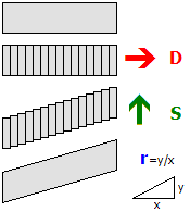
剪切映射以原点为中心进行。不严谨地说,将物体沿方向D切成平面,然后沿方向S移位。通常,D和S是垂直的。D和S都被折算为单位向量。如果 r 为0,则不执行转换。如果D和S垂直,则 r 的1值对应45度的斜率。
MirrorAll X, Y, Z
Y: Whether the y-axis should be mirrored. The default value is 0 (false).
Z: Whether the z-axis should be mirrored. The default value is 0 (false).
The Mirror command mirrors all vertices that have been created so far in the current CreateMeshBuilder section via the AddVertex, Cube or Cylinder commands. Subsequent vertices are not affected. The direction(s) to mirror are specified via the X, Y and Z values. You can use as many Mirror commands as desired in a CreateMeshBuilder section.
The MirrorAll command not only affects the vertices generated in the current CreateMeshBuilder section, but also those created in previous CreateMeshBuilder sections. This is useful to insert at the end of the file in order to mirror the whole object.
ColorAll Red, Green, Blue, Alpha
Green: The green component of the color. Measured from 0 (black) to 255 (green). The default value is 255.
Blue: The blue component of the color. Measured from 0 (black) to 255 (blue). The default value is 255.
Alpha: The alpha component of the color. Measured from 0 (transparent) to 255 (opaque). The default value is 255.
The Color command sets the color for all faces that were already created in the current [MeshBuilder] section. If no texture is used, the faces will be colored using the color data as specified by Red, Green and Blue. If a texture is used, the pixels in the texture will be multiplied by the color, where multiplying with black results in black and multiplying with white does not change the color of the texture pixels. Values in-between make the texture pixels darker. When lighting is used in the route, the actual color can change depending on the lighting conditions, but will usually become darker.
The ColorAll command sets the color for all faces that were already created in the current [MeshBuilder] section, and those created in the previous [MeshBuilder] sections.
EmissiveColorAll Red, Green, Blue
Green: The green component of the color. Measured from 0 (black) to 255 (green). The default value is 0.
Blue: The blue component of the color. Measured from 0 (black) to 255 (blue). The default value is 0.
The EmissiveColor command sets the emissive color for all faces that were already created in the current [MeshBuilder] section. The difference between the Color command and the EmissiveColor command is that the Color command is affected by lighting, while the EmissiveColor command is not. Thus, the EmissiveColor command should be used for faces which would emit light themselves, including signals, lamps, windows and the like. The actual color contribution to the faces will be the sum of the light-affected color data and the static emissive color data.
The EmissiveColorAll command sets the color for all faces that were already created in the current [MeshBuilder] section, and those created in the previous [MeshBuilder] sections.
GlowHalfDistance: The distance at which the glow is at 50% of its intensity, measured in meters. The value must be an integer in the range from 1 to 4095, or 0 to disable glow attenuation. The default value is 0.
GlowAttenuationMode: The glow attenuation mode to use. The default is DivideExponent4.
▸ 混色模式 命令中的可用选项:
Additive: The faces are rendered additively.
▸ 光衰减模式 命令中的可用选项:
DivideExponent4: The glow intensity is determined via the function x4 / (x4 + GlowHalfDistance4), where x is the distance from the camera to the object in meters.
This command sets the blend mode for all faces in the current [MeshBuilder] section. The Normal mode replaces screen pixels with texture pixels. The Additive mode adds the color of texture pixels to the color of screen pixels, where adding black does not change the screen pixel, while adding white results in white. If GlowHalfDistance is 0, glow attenuation will be disabled, which is the default. If glow attenuation is to be used, GlowHalfDistance represents the distance in meters at which the glow is exactly at 50% of its intensity. When the camera approaches the face, the face will gradually fade out (become transparent). The function used to determine the exact intensity for a given distance can be influenced with the setting of GlowAttenuationMode. DivideExponent2 creates a smoother transition, but will converge to the maximum intensity very slowly, while DivideExponent4 creates a sharper transition which converges more quickly.
▸ WrapMode 的選項:
NighttimeTexture: The file name of the daytime version of the texture to load, relative to the directory the object file is stored in.
此命令将加载材质并将其用于当前CreateMeshBuilder部分中的所有面。文件路径相对于CSV文件所在路径。您也可以使用支持完整Alpha通道的PNG格式,但请尽量不要使用半透明的PNG,因为很吃性能。没有Alpha通道(全不透明)的材质可以与SetDecalTransparentColor命令配合使用来达到性能更好的透明效果。
如果使用了 夜间材质 ,它指定在夜间光照状态(.Brightness 0)下使用的材质,而 日间材质 指定在日间光照状态(.Brightness 255)下使用的材质。两个材质会根据光照状态互相混合(.Brightness 1~254),材质也需要以此来进行设计。如果指定了 夜间材质 ,就必须同时指定 日间材质 。如果没有指定 夜间材质 ,暗光照条件会使日间材质更黑。必须使用SetTextureCoordinates指令设定好材质与各顶点的关系,材质才能被正常显示。
Green: The green component of the color. Measured from 0 (black) to 255 (green). The default value is 0.
Blue: The blue component of the color. Measured from 0 (black) to 255 (blue). The default value is 0.
这条指令为已经创建的所有面指定一个蒙版式的透明色(例如屏蔽门和车窗)。刚刚加载的材质中与指定的 红、绿、蓝 颜色完全相同的像素都会变为透明的。这种蒙版式的透明色比起使用含透明部分的PNG性能高,所以最好绘制全不透明的材质,然后将材质中要透明的部分填为固定颜色,再使用此指令将这些部分“挖空”,而不是使用半透明的PNG。必须使用SetTextureCoordinates指令设定好材质与各顶点的关系,材质才能被正常显示。
This command controls the blending mode when both a daytime and a nighttime texture are specified.
When this is set to false the behavior is as follows:
- The daytime texture is drawn.
- The opacity level for the nighttime texture is calculated from the Track.Brightness value, where a value of 255 produces a fully opaque texture, and a value of 0 produces a fully transparent texture.
- The nighttime texture is drawn.
When this is set to true the behaviour is as follows:
The opacity level for each texture is blended proportionately, so that for example, a Track.Brightness value of 128 would produce an (approximately) 50% blend of each texture and so-on.
X: The x-coordinate of the texture. Integer values correspond to the left/right edge of the texture. If only values between 0 and 1 are to be considered, 0 corresponds to the left and 1 to the right.
Y: The y-coordinate of the texture. Integer values correspond to the top/bottom edge of the texture. If only values between 0 and 1 are to be considered, 0 corresponds to the top and 1 to the bottom.
This command associates a coordinate in the texture to the vertex specified by VertexIndex. The index corresponds to the order in which the vertices have been created by the Vertex command, thus the Coordinates command needs to be stated after the corresponding Vertex command. The X and Y values do not necessarily need to be in the range between 0 (left or top) to 1 (right or bottom), but can have any other value. It is assumed in this case that the texture is repeated on an infinite grid where integer values for X and Y correspond to the corners of the texture.