British Signals and Signs
1. Basic Signalling

A basic British color-light signal may contain up to four signal aspects. These aspects include:
| Aspect | Meaning |
|---|---|
| Red | Stop |
| Yellow | Caution (Prepare to stop) |
| Yellow- Yellow | Next signal at caution |
| Green | Proceed |
Alternatively, you may encounter semaphore signals. These come in two basic variants:

A ‘Home’ signal has a red arm, with a white band approximately 2/3 of the way towards the end.
When the arm is horizontal, the signal is at STOP. When the arm has rotated through 45 degrees (This may be either up or down), the signal is at CLEAR.

A ‘Distant’ signal has a yellow arm, with a triangular cutout, and a black band approximately 2/3 of the way towards the end.
These signals provide an advanced warning of the position of the next home signal.
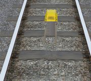
2. Route Speed Limits


There are two basic variants of route speed limit signs, as shown in these images.
Both of these sets of signs update the route speed, expressed as a value in mph.
-
If the new route speed limit is lower than the old one, the new route speed limits takes effect immediately upon passing the speed post with the front of the train.
-
If the new route speed limit is higher than the old one, the whole train must have passed the sign first before the new route speed limit takes effect.
3. AWS
AWS (Automatic Warning System) is a British safety system intended to prevent the train from passing a red signal by applying the emergency brake if the driver does not acknowledge alarms in time.
About 180 meters from a signal, an AWS magnet is placed ( Note: On sections of the West Coast Main Line with a permissiable speed of above 100mph this distance is increased to 230m ). If the signal is red, the ‘AWS Horn’ sounds continously in the cab, and the ‘AWS Sunflower’ instrument will show. If the signal is clear, the ‘AWS Bell’ sounds once, and the ‘AWS Sunflower will remain dark.
-
The AWS Horn must be acknowledged within 3 seconds, or otherwise, an emergency brake application will be performed.
-
In order to acknowledge the alarm, you should press the SECURITY_A1 (insert) key.
-
If you do not acknowledge the AWS Horn in time, the train will be braked to a halt, and you will be unable to cancel the AWS Horn or brake application until the train is at a stand. NOTE: If the train is also fitted with TPWS (See below), you will be unable to release the brakes for a period of 60s after their application.
-
To release an AWS brake application, press the SECURITY_A2 (delete) key.
An AWS magnet may also be placed in advance of the commencement of either a permenant or temporary speed restriction.
These magnets will always generate an AWS Warning, and are intended to remind the driver that they are approaching the speed restriction, and must consider braking appropriately. They should be acknowledged using the procedure described above.
4. TPWS
TPWS (Train Protection and Warning System) is a British safety system intended to prevent the over-running of red signals.
TPWS is always used in conjunction with AWS.

The main parts of the track mounted TPWS equipment are the ‘Overspeed Sensor’ (OSS) speed trap inductors, and the ‘Trainstop Sensor’ (TSS) speed trap inductors. Each sensor comprises an ‘Arming Loop’ and a ‘Trigger Loop’.
The inductors are only energised when the signal shows a red aspect. When the train approaches a red signal, and the on-train TPWS receiver passes the ‘Arming Loop’, the on-train equipment is activated, and it measures the time taken to reach the ‘Trigger Loop’. If the ‘Trigger Loop’ is reached too quickly, then the TPWS knows the train is travelling too fast, and the system will automatically make an ‘OSS Brake Demand’, bringing the train to a halt. The distance between the OSS inductors varies, and the distance determines the maximum speed at which the on-train equipment makes an OSS brake demand.
The ‘Trainstop Sensor’ (TSS) is also energised only when a red aspect is showing. It works in a similar way to the OSS, but regardless of speed, a train passing energised TSS inductors will cause the on-train TPWS equipment to make a ‘TSS Brake Demand’, bringing the train to a halt.
OSS speed traps may also be used in locations other than signal approaches. For example, an OSS speed trap may be placed at the entry to a bay platform to keep approach speed in check, or at the start of a speed restriction where the approach speed is at least 60mph, and the reduction in speed is at least a third of the approach speed.
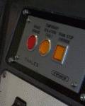
The TPWS equipment visible in the cab consists of a control panel with illuminated buttons and/or indicator lights:
-
The red button is the TPWS Brake Demand indicator. This flashes red when an OSS or TSS Brake Demand is made, but can be made to glow solid red by pressing the AWS Reset button after a TPWS Brake Demand is made.
-
The middle yellow button/indicator is the TPWS Temporary Isolation/Fault indicator. If the TPWS is isolated or has a fault, this will illuminate yellow.
-
The square yellow button is the TPWS Train Stop Override button/indicator. When this is activated, the light illuminates, and the safety system is temporarily overriden to allow one TPWS equipped signal at danger to be passed without a brake demand being made, or until 20 seconds have elapsed after which TPWS returns to normal operation. You may need to activate the Train Stop Override if you received authorisation to pass a signal at danger, perhaps because of a signalling fault. This should only be done with authorisation from a signaller.
Under normal circumstances, you should never see any TPWS indicators illuminated, apart from during the startup/self-test procedure.
If however you approach a red signal too fast, you will trigger an OSS Brake Demand; if you pass a signal at danger (commit a SPAD) then a TSS Brake Demand will be triggered, and if you fail to acknowledge an AWS warning with the AWS Reset button in time, an AWS Brake Demand will be triggered.
When a Brake Demand is triggered, the TPWS Brake Demand indicator will flash red, emergency brakes will be applied, and the train will stop. You can’t cancel the Brake Demand or release the brakes until a 60 second timeout has occured, after which the TPWS Brake Demand indicator extinguishes, and you can proceed.