➟ 快速進行瀏覽…
目錄
- 1. Overview
- 2. Syntax
- 3. Preprocessing
- 4. The Options namespace
- 5. The Route namespace
- 6. The Train namespace
- 7. The Structure namespace
- 8. The Texture namespace
- 9. The Cycle namespace
- 10. The Signal namespace
- 11. The Track namespace
■ 1. 總概
CSV格式的路線是由純文字檔案建立成路線。
這純文字檔案是可以以任意 編碼,但建議使用UTF8-BOM。 數字的 解析方法 是 寬鬆 (Loose)(除非另有說明),但我們還是鼓勵您使用 嚴謹 (Strict) 輸出。 該檔案必須放在包含 Railway 或 Train 的資料夾中。 檔案可随意命名,但必須具有擴展名**.csv**。 該文件以每行為基礎,從上到下進行分析,每一行從左到右分析。
路線文件由一系列命令組成,這些命令定義了在整個用來導入線路中用到的模型 (Structure)。 還可以定義路線,要使用的默認火車和要使用的背景圖像的其他屬性。 最後,路線文件將包含來自Track名稱空間的指令。 此處,軌道位置(通常以米為單位)用於定義軌道何時彎曲,何時放置樁,何時開始和結束牆體等等。 一般而言,在使用來自任何其他命名空間的指令之後,應使用來自Track命名空間的指令。
這個格式默認了一條遊戲默認的主軌道 (0號軌道), 不可以指定它開始的位置, 都不可以完。 遊戲中其他軌道同不同的是, 它由路線的開始一直延續到路線的終點, 代表著玩家駕駛的列車行駛的軌道。 除此之外, 遊戲中定義的其他軌道都是裝飾, 玩家不能行駛的。 不過可以使用 跟隨軌道物件 Track Following Object 來給 AI 列車在其它軌道上行駛。
可以幾何意義上曲同抬升默認的主軌道, 而其他軌道都是相對於主軌道定義的, 並隨主軌道曲起伏。 除非特別修改定義, 線路中每25米劃分為一個區間, 特定的命令只有在區間蚊的邊界位置 (成25米位置) 才能發揮作用。 物體的放置 (尤其是在彎道上) 成日基於一個坐標是, 它的軸並不隨軌道彎曲, 而是掂掂地指向鄰近的下一個區間。
➟ [可以查閱這個 CSV 格式的參考手冊。] (/zh_hk/routes/csv_quick.html)
■ 2. 語法
對於路線文件中每一行, 開頭和結尾的 空格 會被忽略。 然後,每行指令都會㩒逗號 (U+002C) 分割。 于是, 每行都會被看作這樣一個格式:
表達式內容主要有以下類別:
● 註釋
遊戲會自動忽略註釋 (comment)。以分號(” ; “, U+003B) 開頭的表達式都會被視為註釋。
● 軌道位置同長度
一個非負的 嚴格格式 浮點數,代表一個主軌道位置。隨後的指令都將以此位置作為基準點。
是一個配合 Options.UnitOfLength 的更加複雜的距離指定格式, 可用于非公制計量單位。 每一個 * 部分i* 都是 嚴格格式 的浮點數。 *部分1* 會比搭返 *是數 1 *,* 部分2* 搭返 * 是數 2*, 以此類推, 真正的主軌道位置是所有的和。 這個結果一定是非負的。 各部分被冒號 (U+003A) 分隔。 如果想了解如何設定系數, 請參見 Options.UnitOflength 節。
在任何參數中使用距離的命令中,這個冒號表示法就可以被使用,到時我們會用綠色標示呢種情況。
當 n 個單位系數被使用 Options.UnitOflength 定義, 但是使用冒號表示法時輸入的部分卻少了, 咁呢啲系數將會被嚮右匹配, 在左邊的會被忽略。 因此, 幾種表示方法是等傚的: 0:0:2,0:2, 同 2.
● 指令
無參數的指令:
含有參數的指令:
有參數仲有後綴同編號的指令:
規則:
指令名稱 是大小寫都可以的。 編號和參數被分號 (U+003B) 隔開。 指令名稱、編號和參數都在周圍的空格都是被忽略的, 括號周圍的空格都是被忽略的。
如果要使用編碼, 它必須被成對括號 (U+0028, 鍵盤上面9) 和 (U+0029, 英文半角, 鍵盤0上面嗰個) 括起來。 在使用編碼時至少要提供一個參數和一個 后缀。
有兩個使用參數的方法變種, 除了 $ 開頭的預處理指令 ($chr, $rnd, $sub,…) 之外, 可以按照個人喜好二選一。 第 1 種方法: 參數被至少一個空格 (U+0020, 平時用嗰個) 和編碼、指令的大名與及 * 后缀 * 分開。 第 2 種方法: 參數被成對括號 (U+0028, 英文半角在鍵盤9上面嗰個) 和 (U+0029, 在鍵盤0上面嗰個) 括起來。 系第二種方法中, 當使用編碼時就必須使用 * 后缀 *。 在參數周圍的空格都會被忽略。
請注意在有些指令中, 不管是用邊種表示方法, 后缀 都是必需的。 在接下來的文檔中, 必需的 后缀 將被 加粗, 對於第一種方法加不加均可的后缀將被使用灰色表示。
With 語法
All subsequent commands that start with a period (U+002E) are prepended by Prefix. For example:
| ▶ |
With Route .Gauge 1435 .Timetable 1157_M |
相當於
| ▶ |
Route.Gauge 1435 Route.Timetable 1157_M |
■ 3. Preprocessing
在遊戲開始解析線路文件之前, 預處理指令將會被處理定替換。 預処理器會按照正常柯打分析呢啲以 $ 開頭的預処理命令。 $chr、$rnd 和 $sub 指令可以由嵌套, $if、$else 和 $endif 不能出現在另一個指令的括號入面。
預處理指令的語法不可以隨意使用, 必須遵循以下面的形式。
該指令按照權值隨機選出一個線路文件, 再將其內容導入本線路中。 因為該文件內容會比不加修改直接在該指令的位置插入, 可能需要照顧吓 with 指令等, 不好畀佢們出現衝突。 如果參數中最後一個文件冇畀出權值, 它會被按1處理。
$include 指令在幾個線路有大量重複內容時很有用, 可以單獨存入另一個文件只重複內容, 然後在主文檔中導入它, 以方便編碼。 這個指令都可以被用來隨機選取線路代碼。 請注意導入的文件中都可以包含 $include 指令來引用更多的文件, 但是應該避免循環引用, 例如 A 導入 B 而 B 又導入 A。 要導入那個文件不應該使用 .csv 作為格式擴展名 (或者用. include 是個方便區分好主意), 不然玩家可能會一不小心從主 菜單損了這個 “不完全的線路文件” 然後發現冇辦法加载 (除非那個文件本身就是一個單獨的路線, 然後本來就想讓玩家加载它)。
如果任何一個 * 文件i* 被一個: * 主軌道位置偏移量 * 后缀, 嗰個文件中所有主軌道位置表達式都會被按照這個量 ** 以米做單位 ** 偏移。 例如, $include (stations.include:2000) 會將 stations.include 文件中的所有內容系插入前都向前偏移2000米。 需要注意這些主軌道位置表達式是在所有的預処理命令都被執行完先會畀做偏移處理。 意味着似 “1$rnd (2;8) 00” 這樣的主軌道位置表達式即管在預処理前都不是一個主軌道距離表達式, 但是它的隨機結果照樣會被進行偏移處理。
只有OpenBVE1.2.11版以上支持“主軌道位置偏移量”。
這個指令會在原位插入一個對應 ascii 碼 的字符。 如果想在某個地方放置一個字符卻又不想破壞指令語法結構 (比如企名入面開頭帶空格、帶括號逗號分號等, 如果不咁加入就會被遊戲誤讀), 可以使用這個指令。 有關的字符有:
| 編號 | 意思 | 字符 |
|---|---|---|
| 10 | 新一行 | newline |
| 13 | 新一行 | newline |
| 20 | 空格 | space |
| 40 | 開括號 | ( |
| 41 | 閂括號 | ) |
| 44 | 逗號 | , |
| 59 | 分號 | ; |
“$Chr(13)$Chr(10)“代表一次換行。插入$Chr(59)可能基於佢的位置被解釋為註釋開始或指令參數分隔符。
這個指令會在原位插入一個位於 最小值 和 最大值 之間的隨機整數。 可以用這個嚟畀線路添加一些隨機性。
| Example for the use of the $Rnd directive: | |
| ▶ | 10$Rnd(3;5)0, Track.FreeObj 0; 1 |
| Possible outcome from the previous example is exactly one of these lines: | |
| ▶ |
1030, Track.FreeObj 0; 1 1040, Track.FreeObj 0; 1 1050, Track.FreeObj 0; 1 |
這個指令只應該單獨出現, 它將會把 * 表達式 * 的值賦給編號為 * 編號 * 的這個變量。 佢不在原位插入任何內容。 可以將一個隨機數存起來然後之後多次使用。 下面關於 $sub (編號) 的介紹處有幾個使用實例。
程序實現備註
雖然變量中都可以儲埋非數字的內容, 還是不能把逗號通過 $chr (44) 存返入去然後希望它在使用時會起分隔符的作用。 但是, 可以透過 $chr 啲分號 (59) 存返入去然後將調用時放佢在開頭令一行成為註釋。 不過因為可以使用 $include 和 $if 嚟進行條件判斷, 所以並無必要噉做。
這個指令會在原位插入編號為 * 編號 * 的變量的內容。 在讀取前這個變量必須先被賦值。
| Example for the use of the $Sub(Index)=Value and $Sub(Index) directives: | |
| ▶ |
$Sub(0) = $Rnd(3; 5) 1000, Track.FreeObj $Sub(0); 47 1020, Track.FreeObj $Sub(0); 47 1040, Track.FreeObj $Sub(0); 47 |
在這個例子中, 三個 track.freeobj 指令都使用同樣的隨機數值, 所以三個物體會被擺在同一條隨機的軌道邊。 如果使用三個 $rnd (3;5) 而不是 $sub, 三個物體可能被單獨放在不同的軌道邊
$if (如果…… 那麼) 指令讓遊戲只在這個條件成立, 即為非零值時才解析下面的線路指令。 $if 的後面必須有一個 $endif。 在 $if 和 $endif 之間都可以加個 $else 嚟表示條件是不成立既時候要解析的指令。
$Else (否則) 指令只在前面的 $If 的條件是不成立既時候先解析下面的線路指令。
$EndIf 指令標識前面的 $If 指令的影響範圍到此結束。
| Example of $If, $Else and $EndIf | |
| ▶ |
$Sub(1) = 0 With Track $If($Sub(1)) 1020, .FreeObj 0; 1 1040, .FreeObj 0; 2 $Else() 1030, .FreeObj 0; 3 $EndIf() |
| Another example of $If, $Else and $EndIf | |
| ▶ |
With Track 1050 $If($Rnd(0;1)), .FreeObj 0; 4, $Else(), .FreeObj 0; 5, $EndIf() |
可以嵌套 $If 指令。 如果將 $If/$Else/$EndIf 擺在不同的幾行度, 可以更清晰地表示張結構並令它更易讀 (例如第一個例子)。
最後, 當預處理結束, 線路中的所有指令都會被按照軌道位置重新排序。
| Example of a partial route file: | |
| ▶ |
1000, Track.FreeObj 0; 23 1050, Track.RailType 0; 1 10$Rnd(3;7)0, Track.Rail 1; 4 Track.FreeObj 1; 42 |
| Preprocessing the $Rnd directive (assuming 3 is produced): | |
| ▶ |
1000, Track.FreeObj 0; 23 1050, Track.RailType 0; 1 1030, Track.Rail 1; 4 Track.FreeObj 1; 42 |
| Sorting by associated track positions: | |
| ▶ |
1000, Track.FreeObj 0; 23 1030, Track.Rail 1; 4 Track.FreeObj 1; 42 1050, Track.RailType 0; 1 |
■ 4. Options 命名空間
這個命名空間入面的指令設置一些基本設置, 並影響其他指令既實際處理效果。 所以應當在開始編寫寫其他指令之前使用這些指令都較只設置先掂。
這個指令可以被用來改變其他指令使用的長度單位。 當同形如 * 部分1*:* 部分2*:…:* 部分n* 的主軌道位置一起使用時, * 部分i* 會比搭返 * 系數 i*, 以此類推, 真正的主軌道位置是所有積的和。 更改了長度單位時, 你都應同時使用 Options.BlockLength 將區間蚊長度也設為相應單位。
換算系數的幾個示例:
| 所需單位 | 轉換是數 |
|---|---|
| 英里 | 1609.344 |
| 引 | 20.1168 |
| 米 | 1 |
| 市丈 | 0.9144 |
| 英尺 | 0.3048 |
在下面的示例中, 會被 Options.UnitOfLength 影響的指令參數會被用綠色表示。
這個指令可以被用來改變其他指令使用的速度單位。 換算系數的幾個示例:
| 單位 | 換算是數 |
|---|---|
| 米每秒 | 3.6 |
| 英里每小時 | 1.609344 |
| 千米每小時 | 1 |
在下面的例子中, 可被 Options.UnitOfSpeed 影響的指令參數會被藍色表示。
此指令可以設置隔蚊的長度。 是一個全局設置, 一旦設置, 不可以來回更改。 如果在此指令之前調用了選項. 單位長度, 長度 將使用選項. 單位長度作為單位。
▸ 模式 的選項:
▸ 模式 的選項:
▸ 模式 的選項:
▸ 模式 的選項:
1: Interpolated: Fog color and ranges are interpolated between adjacent Track.Fog commands. This behavior mimicks Track.Brightness.
▸ 模式 的選項:
1: On: Fuzzy matching. If the texture uses a restricted color pallet, the transparent color will be clamped to the nearest available color in the pallet.
▸ 模式 的選項:
1: On: Hacks are enabled.
■ 5. The Route namespace
Commands from this namespace define general properties of the route.
如果需要插入換行、逗號之類的字符,必須使用$Chr。
如果需要插入換行、逗號之類的字符,必須使用$Chr。
▸ 模式 的選項:
1: 安全系統 未啟動,並且已應用了 緊急 制動器。
Train.Gauge 是同 Route.Gauge 一樣
Speed: A non-negative floating-point number representing the allowed speed for this aspect, by default measured in kilometers per hour (km/h).
Use this command to associate speed limits to signal aspects. Aspect 0 represents a red signal, higher values represent more permissive aspects. The default values (for the included Japanese signals) are:
| Index | Aspect | Speed |
|---|---|---|
| 0 | ● | 0 km/h |
| 1 | ●● | 25 km/h |
| 2 | ● | 55 km/h |
| 3 | ●● | 75 km/h |
| 4 | ● | 無限 |
| 5 | ●● | 無限 |
This command creates one or more preceding or following trains. These other trains are visible, fully operational, and use the same train as the player has. The other trains follow the same schedule as the player does, but are offset in time by Intervali. Via the Track.Sta command, you can also define stations where only the player or only the other trains should stop. Follow-up trains only appear once the section they are placed in has been cleared by other trains, but the player’s train is introduced regardless of the current signalling section’s state. Therefore, you should make sure that other trains have cleared the area where the player’s train will appear when the scenario begins.
Route.RunInterval 是同 Train.Interval 一樣
This command allows speed related messages (overspeed etc.) to be displayed in a custom unit, for example mph.
此指令允許將自定圖片設為加載時的背景。
This command allows the start time of the simulation to be set.
If this is not set or is invalid, the simulation will start at the arrival time set at the first station.
This command may be used as an alternative to the Route.AmbientLight , Route.DirectionalLight and Route.LightDirection commands.
It allows the lighting to be varied using a time-based model, and is described fully on the following page:
GreenValue: An integer ranging from 0 to 255 representing the green component of the ambient light. The default value is 160.
BlueValue: An integer ranging from 0 to 255 representing the blue component of the ambient light. The default value is 160.
This command defines the ambient light color to be used. All polygons in the scene are illuminated by the ambient light regardless of the light direction.
GreenValue: An integer ranging from 0 to 255 representing the green component of the directional light. The default value is 160.
BlueValue: An integer ranging from 0 to 255 representing the blue component of the directional light. The default value is 160.
This command defines the directional light to be used. The polygons in the scene are only fully illuminated by the directional light if the light direction points at the front faces. If pointing at back faces, no light is contributed. Route.LightDirection should be set to specify the light direction.
Phi: A floating-point number representing the angle in degrees which controls the planar rotation of the light direction. The default value is about -26.57.
This command defines the initial light direction for track position 0. This is the direction the light shines at, meaning the opposite direction the sun is located at. First, Theta determines the pitch. A value of 90 represents a downward direction, while a value of -90 represents an upward direction. With those extremes, the value of Phi is irrelevant. A value of 0 for Theta represents a forward direction originating at the horizon behind. Once the pitch is defined by Theta, Phi determines the rotation in the plane. A value of 0 does not rotate, a value of 90 rotates the direction to the right and a value of -90 rotates to the left. A backward direction can be both obtained by setting Theta and Phi to 180 and 0 or to 0 and 180, respectively. Values in-between allow for more precise control of the exact light direction.
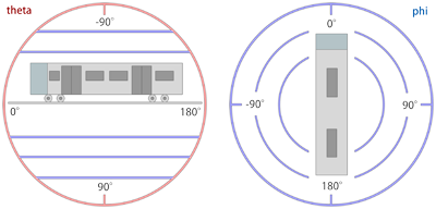
| Converting a spherical direction (theta,phi) into a cartesian direction (x,y,z): | |
| ƒ |
x = cos(theta) * sin(phi) y = -sin(theta) z = cos(theta) * cos(phi) |
| Converting a cartesian direction (x,y,z) into a spherical direction (theta,phi) for y2≠1: | |
| ƒ |
theta = -arctan(y/sqrt(x2+z2)) phi = arctan(z,x) |
| Converting a cartesian direction (x,y,z) into a spherical direction (theta,phi) for y2=1: | |
| ƒ |
theta = -y * pi/2 phi = 0 |
In the formulas above, cos(x) represents the cosine, sin(x) the sine, arctan(x) the inverse tangent, arctan(x,y) the two-argument inverse tangent and sqrt(x) the square root. The formulas can be used to convert between spherical and cartesian coordinates if working with either one seems more intuitive than working with the other one. The formulas also serve as the official documentation on how the light direction is mathematically defined (using radians for the trigonometric functions).
0 : The camera will be placed in the cab. (Default)
1 : The camera will be placed in ‘Exterior Camera’ mode.
2 : The camera will be placed in ‘Track Camera’ mode.
3 : The camera will be placed in ‘Flyby Camera’ mode.
4 : The camera will be placed in ‘Flyby Zooming Camera’ mode.
This command allows the route developer to place the initial camera in one of the alternate camera modes.
這個命令是會比OpenBVE忽略
■ 6. The Train namespace
Commands from this namespace define route-train associations.
Train.File FolderName
Train.Rail(RailTypeIndex).Set RunSoundIndex
RunSoundIndex: A non-negative integer representing the train’s run sound to associate to the rail type.
The train developer provides a repertoire of different run sounds. Use this command to associate these run sounds to the rail types you use in your route. In order for the correct run sounds to be played on any of your rail types, you need to coordinate your efforts with the train developer. Please see the page about standards for further information.
FlangeSoundIndex: A non-negative integer representing the train’s flange sound to associate to the rail type.
The train developer provides a repertoire of different flange sounds. Use this command to associate these flange sounds to the rail types you use in your route. In order for the correct flange sounds to be played on any of your rail types, you need to coordinate your efforts with the train developer. Please see the page about standards for further information.
FileName: The file name for the daytime version of the timetable, relative to the train’s folder (1st choice), or relative to the Object folder (2nd choice).
Use this command to load daytime versions of the timetable. Which timetable index to show starting with a particular station can be set in Track.Sta commands.
FileName: The file name for the daytime version of the timetable, relative to the train’s folder (1st choice), or relative to the Object folder (2nd choice).
Use this command to load nighttime versions of the timetable. Which timetable index to show starting with a particular station can be set in Track.Sta commands.
Train.Gauge 是同 Route.Gauge 一樣
Train.Interval 和 Route.RunInterval 是一樣的
This command defines the maximum speed limit the preceding trains may travel at. The actual speed limit may be reduced by Track.Limit commands. The player’s train is unaffected by this setting and may travel up to the limits defined by Track.Limit.
這個命令是會比OpenBVE忽略
這個命令是會被OpenBVE忽略
■ 7. The Structure namespace
The commands in the Structure namespace define which objects to use in other commands. Generally, commands like Track.Rail, Track.FreeObj and so on create objects referenced by a StructureIndex. This StructureIndex is specific to that command, so you can define a set of objects specific to Track.Rail, Track.FreeObj and so on.
The general syntax for commands in the Structure namespace is:
StructureIndex is a non-negative integer. FileName is the object file to load, relative to the Object folder. Command is any of the following commands:
| Command: | Remarks |
|---|---|
| Ground | Defines objects for Cycle.Ground and Track.Ground. |
| Rail | Defines objects for Track.Rail, Track.RailStart and Track.RailType. |
| WallL | Defines left objects for Track.Wall. |
| WallR | Defines right objects for Track.Wall. |
| DikeL | Defines left objects for Track.Dike. |
| DikeR | Defines right objects for Track.Dike. |
| FormL | Defines left platforms edges for Track.Form. |
| FormR | Defines right platforms edges for Track.Form. |
| FormCL | Defines transformable left platforms for Track.Form. No ANIMATED objects supported. |
| FormCR | Defines transformable right platforms for Track.Form. No ANIMATED objects supported. |
| RoofL | Defines left roof edges for Track.Form. |
| RoofR | Defines right roof edges for Track.Form. |
| RoofCL | Defines transformable left roofs for Track.Form. No ANIMATED objects supported. |
| RoofCR | Defines transformable right roofs for Track.Form. No ANIMATED objects supported. |
| CrackL | Defines transformable left objects for Track.Crack. No ANIMATED objects supported. |
| CrackR | Defines transformable right objects for Track.Crack. No ANIMATED objects supported. |
| FreeObj | 為Track.FreeObj定義物件。 |
| Beacon | Defines objects for Track.Beacon. |
| 天氣 | 为使用 Track.Rain 和 Track.Snow 生成的天气定义对象。 |
| 动态光 | 定义动态照明集。 |
Generally, supported objects are B3D, CSV, X and ANIMATED. However, the FormCL, FormCR, RoofCL, RoofCR, CrackL and CrackR commands only accept B3D, CSV and X objects.
➟ More information about forms, roofs and cracks…
Additionally, there is the Structure.Pole command, which has a slightly different syntax:
PoleStructureIndex: A non-negative integer representing the pole structure index.
FileName: The object file to load, relative to the Object folder.
Please note that all objects but the FreeObj are inserted at the beginning of a block and should thus extend from 0 to BlockLength (by default 25m) on the z-axis. For further information on usage, see the respective commands from the Track namespace.
■ 8. The Texture namespace
Commands from this namespace define which background images to use and how they are aligned.
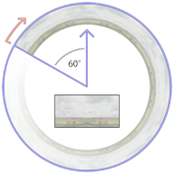
The background image is displayed as a cylindric wall around the camera whose start (viewed from above) is 60 degrees to the left of the initial forward direction (at the 10 o’clock position). From there, the background image wraps clock-wise around the cylinder with a repetition count specified via Texture.Background(BackgroundTextureIndex).X, which by default creates 6 repetitions in a full circle.
The upper 3/4 of the image is displayed above the horizon, while the lower 1/4 is displayed below the horizon. Via Texture.Background(BackgroundTextureIndex).Aspect, you can choose whether to have a fixed cylinder height or to preserve the aspect ratio of the texture. If the image should have a fixed height, the cylinder has a height of 1/2 its radius, which corresponds to about 20 degree inclination to the top of the image, and about -7 degrees to the bottom of the image. If the aspect ratio of the image is preserved, this takes not only the width and height of the image into account, but also the repetition count.
Regardless of the repetition count you chose, you should make sure that the left and right edges of the textures fit seamlessly together. Please also take into account that top and bottom caps are created which sample from the top and bottom 10% of the image. You should avoid mountain peaks and similar extremes in the top 10% of the image in order for such extremes to not leak into the top cap.
The image loaded into Texture.Background(0) is displayed at the beginning of the route, unless a Track.Back command at the beginning of the route requests a different image.
As an alternative Dynamic or Object based backgrounds may be used. The implementation of these is described upon this page:
Dynamic & Object Based Backgrounds
This command loads a background image to be later used by Track.Back.
If a dynamic or object based background is to be used, this must instead point to the appropriate XML file.
Ignored if using a dynamic or object based background.
▸ Options for Mode:
1: Aspect: Preserve the aspect ratio of the image.
Ignored if using a dynamic or object based background.
■ 9. The Cycle namespace
GroundStructureIndexi: A non-negative integer indicating a ground structure that has been previously loaded via Structure.Ground.
When usually using Track.Ground(GroundStructureIndex), the same ground structure object will be repeatedly placed in every block. Via Cycle.Ground, you can override this behavior and automatically cycle through a series of different objects when using Track.Ground(GroundStructureIndex). The cycle repeats indefinitely, where GroundStructureIndex0 starts at track position 0. Technically, the i in GroundStructureIndexi chosen for a particular track position p is Mod[p / BlockLength, n].
RailStructureIndexi: A non-negative integer indicating a rail structure that has been previously loaded via Structure.Rail.
Consider the following definition:
| ▶ |
With Structure .Ground(0) grass.csv .Ground(1) river.csv .Ground(2) asphalt.csv |
The following two codes will produce the same output:
| ▶ |
With Track 0, .Ground 0 25, .Ground 1 50, .Ground 2 75, .Ground 0 100, .Ground 1 125, .Ground 2 ; and so on… |
| ▶ |
With Cycle .Ground(0) 0; 1; 2 With Track 0, .Ground 0 |
■ 10. The Signal namespace
Commands from this namespace define custom signals.
AnimatedObjectFile: A reference to an animated object file, relative to the Object folder.
Use this command to load signals directly from animated objects. The SignalIndex can be later referenced in Track.SigF commands to place the signal.
SignalFileWithoutExtension: A reference to a B3D/CSV/X object file representing the signal, relative to the Object folder, but without the file extension. Is required to be specified.
GlowFileWithoutExtension: An optional reference to a B3D/CSV/X object file representing the distance glow, relative to the Object folder, but without the file extension.
Use this command to load signals from a series of individual textures applied onto a common object. openBVE looks for X, CSV and B3D objects in this exact order. Textures are required to have the same name as the signal or glow, plus a non-negative aspect index, plus a file extension for textures. The SignalIndex can be later referenced in Track.SigF commands to place the signal.
For the SignalFileWithoutExtension, there should be the following files present (example):
SignalFileWithoutExtension.x
SignalFileWithoutExtension0.bmp
SignalFileWithoutExtension1.bmp
SignalFileWithoutExtension2.bmp
SignalFileWithoutExtensionn.bmp
The aspect indices from 0 through n represent successively more permissive aspects, where 0 is red. The built-in signals, for example, use the indices 0 (●), 1 (●●), 2 (●), 3 (●●), 4 (●) and 5 (●●). You can use as many as required.
All faces in the object will be applied the currently active aspect texture. This means that you cannot use any other texture in the object, but still have to assign texture coordinates appropriately. For the glow object, the above rules also apply. The glow object is usually a rectangle placed clearly in front of the signal, although you can also use different shapes.
The glow textures deserve special attention. All glow textures are pre-processed in the following way:
| A | B | C | D | E | F |
|---|---|---|---|---|---|
 |
 |
 |
 |
 |
 |
The texture you start with should have a sharp shape, usually oval. The shape should be fully saturated in the core and blend into pure white at its outer rim. The surroundings of the shape can be either pure black (A) or pure white (B).
When openBVE loads the glow texture, it will replace all purely black pixels with purely white pixels, thus arriving at (B). From there, the image is inverted (C), then hue-shifted by 180 degrees (D). Compared to (B), this has the overall effect of inverting the lightness of the image, i.e. fully saturated pixels will be left unchanged (e.g. the core), while bright pixels (such as the outer rim of the shape) will become dark, and vice versa. Then, the image is gamma-corrected to further darken the dark parts (E), and finally, the image is blurred slightly (F).
The resulting texture is always additively blended. This means that instead of directly drawing the texture onto the screen, the pixels of the texture are added to the screen pixels. Here, adding black (0) does not change the screen pixels, while adding a fully satured color channel (1) will result in a fully satured color channel, e.g. adding white produces white. Keep in mind that when designing the textures, you will have to follow the inverse rules, e.g. design the image as depicted in (A) or (B), while having in mind how it will be processed afterward.
■ 11. Track指令命名空間
Commands from this namespace define the track layout. Commands from this namespace should appear after commands from any of the other namespaces, and they usually form the largest part of the route file.
Use of track positions
All commands from the Track namespace need to be associated to track positions. Once a track position has been defined, all subsequent commands are associated to this track position until a new track position is defined. If you do not explicitly state a track position before the first command of the Track namespace is used, 0 will be assumed. While you do not need to use track positions in ascending order, series of commands which are associated the same track position will be sorted into ascending order once the file is loaded. While track positions can be any non-negative floating-point number, many commands in the Track namespace are only to be applied at the beginning of a block, which is 25m by default. For the default situation, this means that some commands are only to be used at track positions 0, 25, 50, 75, 100, 125 and so on. All commands for which this restriction applies are marked as such.
● 11.1. Rails
X: A floating-point number representing the horizontal distance from the player’s rail, by default measured in meters. Negative values indicate left, positive ones right.
Y: A floating-point number representing the vertical distance from the player’s rail, by default measured in meters. Negative values indicate below, positive ones above.
RailType: A non-negative integer referencing the rail type to use as defined by either a Structure.Rail or a Structure.Cycle command.
This command starts a new rail represented by the index RailIndex. Upon the point where this command is used, a rail of the same RailIndex must either not have been used so far in the route, or must have been ended via a Track.RailEnd command. If a rail of the same RailIndex was already used in the route, the default values of X, Y and RailType are the values last used by that rail, otherwise 0. If the rail is to be updated, use the Track.Rail command. If it is to be ended, use the Track.RailEnd command. You can end a rail of a given RailIndex and start a new rail of the same RailIndex at the same track position provided that the old rail is first ended and the new rail started afterward. For every block, a structure, determined by RailType, is automatically placed.
This command can only be used at the beginning of a block.
X: A floating-point number representing the horizontal distance from the player’s rail, by default measured in meters. Negative values indicate left, positive ones right.
Y: A floating-point number representing the vertical distance from the player’s rail, by default measured in meters. Negative values indicate below, positive ones above.
RailType: A non-negative integer referencing the rail type to use as defined by either a Structure.Rail or a Structure.Cycle command.
This command starts a new rail or updates an existing rail. The rail is represented by the index RailIndex. If a rail of the same RailIndex was already used in the route, the default values of X, Y and RailType are the values last used by that rail, otherwise 0. If the rail is to be ended, use the Track.RailEnd command. You can end a rail of a given RailIndex and start a new rail of the same RailIndex at the same track position provided that the old rail is first ended and the new rail started afterward. In each block, the X and Y values are repeated if a Track.Rail command is not used for that block. As a consequence, updating the X or Y values affects the layout of the rail from the preceding block only. Changing the RailType will affect the rail from the point on where this command is used. If this command is used multiple times on the same track position for the same rail, then the first instance of the command takes effect, while subsequent ones are ignored.
This command can only be used at the beginning of a block.
Using a RailIndex value of 0 is not valid for this command: Errata Note
Track.RailStart vs. Track.Rail
If you want to start a new rail, you can either use Track.RailStart or Track.Rail. When using Track.RailStart, you provide markup that a new rail is in fact to be started, which is invalid if the rail already exists. Using an explicit Track.RailStart will protect you from using a RailIndex which is already in use, in which case an error message is generated.
RailType: A non-negative integer referencing the rail type to use as defined by either a Structure.Rail or a Structure.Cycle command. The default value is 0.
This command changes the rail type for an existing rail, represented by RailIndex. The rail must have been started with a Track.RailStart or Track.Rail command and must not have been ended by a Track.RailEnd command. Changing the RailType will affect the rail from the point on where this command is used.
This command can only be used at the beginning of a block.
X: A floating-point number representing the horizontal distance from the player’s rail, by default measured in meters. Negative values indicate left, positive ones right.
Y: A floating-point number representing the vertical distance from the player’s rail, by default measured in meters. Negative values indicate below, positive ones above.
This command ends an existing rail, represented by the index RailIndex. The default values of X and Y are the ones last used by the rail. Once this command is used for a specific RailIndex, the corresponding rail is considered to be non-existing afterward.
This command can only be used at the beginning of a block.
Using a RailIndex value of 0 is not valid for this command: Errata Note
| Example of Track.RailStart, Track.Rail, Track.RailType and Track.RailEnd commands | |
| ▶ |
With Track 1000, .RailStart 1; 3.8; 0.0; 0 1025, .RailType 1; 1 1050, .Rail 1; 1.9; 0.0; 0 1075, .RailEnd 1 |
In the preceding example, rail 1 starts with an x-value of 3.8 and bears a rail index which corresponds to an object intended to depict a straight rail. The rail keeps the x-value of 3.8 at track position 1025, where the rail type is changed to correspond to an object intended to depict an s-shaped curve. At track position 1050, the rail is redefined to have an x-value of 1.9, after which the rail is straight again until 1075, where it is ended, still having an x-value of 1.9.
This command sets the accuracy of the track from this point on. Values should be in the range from 0 to 4, where 0 means perfect accuracy (no inaccuracy at all), 1 means very good accuracy (high speed lines), 2 means good accuracy, 3 means mediocre accuracy, and 4 means poor accuracy. Intermediate values are also possible. Currently, values below 0 are clamped at 0, and values above 4 are clamped at 4.
This command sets the adhesion of the track from this point on. As a reference, the value of 135 represents dry conditions, 85 represents frost and 50 represents snowy conditions. With a value of 0, the train will not be able to move at all.
WeatherType: A non-negative integer referencing the weather type to use as defined by Structure.Weather from this point onwards.
This command sets the intensity of the current rainfall, and the weather object to be shown.
It is also possible to set the rain intensity using the legacy BVE4 beacon based method. If these commands are present in the route, all Rain commands will be ignored.
WeatherType: A non-negative integer referencing the weather type to use as defined by Structure.Weather from this point onwards.
This command sets the intensity of the current snowfall, and the weather object to be shown.
Combining rain and snow
Rain and snow may be combined, and the simulation will show an appropriate random raindrop or snowflake on the windscreen, based upon the following probabilities:
The base probability for a drop / flake to appear is the greater of the rainfall and snowfall intensities.
The snowfall intensity is then used as the probability that this is a snowflake.
For example, with rainfall at 50 and snowfall at 40, there is a 50% chance for a drop to be added to the windscreen on each tick.
Of this, there is a 40% chance that this will be a snowflake.
● 11.2. Geometry
This command defines the pitch of all rails from this point on. Negative values indicate a downward gradient, positive ones an upward gradient. The value of 0 represents a level track. Rate can be calculated from a length difference X and a height difference Y in the following way:
| Rate expressed through X and Y: | |
| ƒ | Rate = 1000 * Y / X |
This command can only be used at the beginning of a block.
CantInMillimeters: A floating-point number which represents the superelevation of a banked curve, always measured in millimeters (0.001 meters). The default value is 0. See also Options.CantBehavior.
This command defines the radius of the curve for the player’s rail from this point on. Negative values for Radius indicate a curve to the left, positive ones to the right. The value of 0 represents straight track. The CantInMillimeters parameter defines the cant (superelevation) in millimeters. If Options.CantBehavior is 0 (default), only the absolute value of CantInMillimeters is considered, and the superelevation is always towards the curve center (inward). Also, cant cannot be applied on straight track. If Options.CantBehavior is 1, CantInMillimeters is signed, i.e. negative values bank outward and positive ones inward on curved track. Also, cant can be applied on straight track, where negative values bank toward the left and positive ones toward the right.
This command can only be used at the beginning of a block.
This command creates a point-based turn at the point of insertion. Ratio indicates the ratio between the length difference Z and the horizontal offset X in the following way:
| ƒ | Ratio = X / Z |
A negative ratio represents a turn to the left, a positive one to the right. The value of 0 represents a straight track.
This command can only be used at the beginning of a block.
This command is deprecated - use Track.Curve instead.
This command defines the height of the player’s rail above the ground at the point of insertion. It influences the placement of the ground objects defined via Structure.Ground and changed via Track.Ground. The height is interpolated between adjacent Track.Height commands. For example, the following two codes produce equivalent results:
| Example of a Track.Height command interpolated at 25m boundaries: | |
| ▶ |
1000, Track.Height 1 1075, Track.Height 4 |
| Example of Track.Height explicitly set each 25m to produce the same result: | |
| ▶ |
1000, Track.Height 1 1025, Track.Height 2 1050, Track.Height 3 1075, Track.Height 4 |
This command can only be used at the beginning of a block.
● 11.3. Objects
FreeObjStructureIndex: A non-negative integer representing the object to place as defined via Structure.FreeObj. The default value is 0.
X: The x-offset from the (straight) rail, by default measured in meters. Negative values represent the left, positive ones the right. The default value is 0.
Y: The y-offset from the (straight) rail, by default measured in meters. Negative values represent below the top of the rails, positive ones above. The default value is 0.
Yaw: The angle in degrees by which the object is rotated in the XZ-plane in clock-wise order when viewed from above. The default value is 0.
Pitch: The angle in degrees by which the object is rotated in the YZ-plane in clock-wise order when viewed from the left. The default value is 0.
Roll: The angle in degrees by which the object is rotated in the XY-plane in clock-wise order when viewed from behind. The default value is 0.
This places a “free” object a single time on a specified rail. The object must have been loaded via Structure.FreeObj(FreeObjStructureIndex) prior to using this command.
Direction: An integer indicating which wall to use as described below.
WallStructureIndex: A non-negative integer representing the object to place as defined via Structure.WallL and Structure.WallR. The default value is 0.
▸ Options for Direction:
0: Both the WallL and WallR objects are used.
1: The WallR object (right wall) is used.
This starts or updates a wall on a specified rail. The object must have been loaded via Structure.WallL(WallObjectIndex) or Structure.WallR(WallObjectIndex) prior to using this command. The walls are placed at the beginning of every block until a corresponding Track.WallEnd ends the wall for this rail. Please note that walls are resurrected if a rail is ended via Track.RailEnd and then started again via Track.RailStart or Track.Rail unless the wall was also ended via Track.WallEnd.
This command can only be used at the beginning of a block.
This ends an existing wall that was previously started via Track.Wall on a specified rail. The wall is not placed for the block in which this command is used.
This command can only be used at the beginning of a block.
Direction: An integer indicating which dike to use as described below.
DikeStructureIndex: A non-negative integer representing the object to place as defined via Structure.DikeL and Structure.DikeR. The default value is 0.
▸ Options for Direction:
0: Both the DikeL and DikeR objects are used.
1: The DikeR object (right dike) is used.
This starts or updates a dike on a specified rail. The object must have been loaded via Structure.DikeL(DikeObjectIndex) or Structure.DikeR(DikeObjectIndex) prior to using this command. The dikes are placed at the beginning of every block until a corresponding Track.DikeEnd ends the dike for this rail. Please note that dikes are resurrected if a rail is ended via Track.RailEnd and then started again via Track.RailStart or Track.Rail unless the dike was also ended via Track.DikeEnd.
This command can only be used at the beginning of a block.
This ends an existing dike that was previously started via Track.Dike on a specified rail. The dike is not placed for the block in which this command is used.
This command can only be used at the beginning of a block.
NumberOfAdditionalRails: A non-negative integer representing the amount of additional rails covered by this pole (i.e. this rail, plus NumberOfAdditionalRails rails). The default value is 0.
Location: If NumberOfAdditionalRails is 0, the side on which the pole is placed (see below), or the x-offset in multiples of 3.8 meters if NumberOfAdditionalRails is at least 1. The default value is 0.
Interval: An integer multiple of the block length specifying the interval in which poles are placed.
PoleStructureIndex: A non-negative integer representing the object to place as defined via Structure.Pole. The default value is 0.
This starts or updates a pole on a specified rail. The object must have been loaded via Structure.Pole(NumberOfAdditionalRails; PoleStructureIndex) prior to using this command. The poles are placed at the beginning of every block whose track positions are an integer multiple of the Interval (that is not necessarily at the same location this command is placed). If NumberOfAdditionalRails is 0, Locationindicates the side of the rail on which the pole is placed. If Location is less than or equal to 0, the pole is placed as-is (corresponding to the left side). If Location is greater than 0, the object is mirrored on the x-axis and then placed (corresponding to the right side). If NumberOfAdditionalRails is greater than or equal to 1, Location specifies the x-offset in multiples of 3.8 meters. Please note that poles are resurrected if a rail is ended via Track.RailEnd and then started again via Track.RailStart or Track.Rail unless the pole was also ended via Track.PoleEnd.
This command can only be used at the beginning of a block.
This ends an existing pole that was previously started via Track.Pole on a specified rail. The pole is not placed for the block in which this command is used.
This command can only be used at the beginning of a block.
This deforms a specified object to fill the space between two Rails.
RailIndex2: A non-negative integer representing the second RailIndex.
CrackStructureIndex: A non-negative integer representing the object defined in Structure.Crack
Note:
If RailIndex1 is to the left of RailIndex2 (e.g. it’s X-cordinate is smaller), then the object defined in Structure.CrackL will be used.
Otherwise, the objects defined in Structure.CrackR will be used.
This defines which ground objects to place from this point on. Ground objects are always placed at the beginning of a block at a certain height below the player’s rail (as defined via Track.Height). If no cycle was defined for CycleIndex, then the object loaded into Structure.Ground(CycleIndex) is placed. Otherwise, the cycle of ground objects as defined via Cycle.Ground(CycleIndex) is used.
This command can only be used at the beginning of a block.
● 11.4. Stations
ArrivalTime: The time the player’s train is expected to arrive at this station. Special values may also appear - see below.
DepartureTime: The time the player’s train is expected to depart from this station. Special values may also appear - see below.
PassAlarm: Indicates whether the pass alarm device should remind the driver of stopping at this station. The default value is 0.
Doors: Indicates which doors should open at this station. The default value is 0.
ForcedRedSignal: Indicates whether the signal behind the last station stop should be red on a train approach. The default value is 0.
System: Indicates which built-in safety system should apply until the next station. The default value is 0.
ArrivalSound: The sound file to be played on arrival, relative to the Sound folder.
StopDuration: A positive floating-point number indicating the minimum stop duration in seconds, including door opening/closing times. The default value is 15.
PassengerRatio: A non-negative floating-point number indicating the relative amount of passengers in the train from this station on. As a reference, 100 represents a train with normal amount of passengers, while 250 represents an over-crowded train. Values in-between 0 and 250 should be used. The default value is 100.
DepartureSound: The sound file to be played before departure (departure time minus sound duration minus door closing time), relative to the Sound folder.
TimetableIndex: A non-negative integer representing the timetable to be shown from this station on as defined via Train.Timetable(TimetableIndex).
▸ ArrivalTime 的選項:
omitted: The train may arrive at any time.
P or L: All trains are expected to pass this station.
B: The player’s train is expected to pass this station, while all other trains are expected to stop.
S: The player’s train is expected to stop at this station, while all other trains are expected to pass.
S:time: The player’s train is expected to arrive at this particular time, while all other trains are expected to pass.
D: This station is a dummy station for use in conjunction with ForcedRedSignal. No stop position overlay or timetable entry will be shown.
▸ DepartureTime 的選項:
omitted: The train may depart at any time.
T or =: This is the terminal station. If ForcedRedSignal is set to 1, the departure signal will be held at red indefinately.
T:time: This is the terminal station. If ForcedRedSignal is set to 1, the departure signal will still switch to green before the specified time as if this was a regular station.
C: This is a station at which to “change ends”. See the description below.
C:time: This is a station at which to “change ends”. Changing ends will take place at the specified time unless StopDuration interferes. See the description below.
J:index: This is a station at which the train is “jumped” to the station specified by index. See the description below.
J:index:Time: This is a station at which the train is “jumped” to the specified by index. Jumping will take place at the specified time unless StopDuration interfers. See the description below.
▸ PassAlarm 的選項:
1: The pass alarm device reminds the driver of stopping at this station.
▸ Doors 的選項:
N or 0: No doors are expected to open at this station, i.e. the train should simply come to a hold.
R or 1: The right doors are expected to open at this station.
B: Both the left and right doors are expected to open at this station.
▸ ForcedRedSignal 的選項:
1: The signal immediately following the last station stop is hold at red until the train reaches the stopping area and the departure time.
▸ System 的選項:
ATC or 1: ATC should be used from this station on. The following track is equipped with ATC.
This command initializes a new station. It should be placed at the beginning of the station platform. In order to finalize the creation of a station, use the Track.Stop command to place stop points following this command. All following Track.Stop commands will be associated to this station. At least one Track.Stop command must follow if trains are expected to stop at this station.
Special Features:
Stations can be marked as “changing ends” in the departure time. At such stations, when the departure time has been reached, the train will automatically jump to the next station. This feature is intended to fake a reverse of traveling direction without the need to jump to stations manually from the menu.
Similarly, stations can be marked as a “jump point” in the departure time. At such stations, when the departure time has been reached, the train will automatically jump to the specified station index.
The first occuring station in a route may not be of the Terminal type.
ArrivalTime: The time the player’s train is expected to arrive at this station. Special values may also appear - see below.
DepartureTime: The time the player’s train is expected to depart from this station. Special values may also appear - see below.
ForcedRedSignal: Indicates whether the signal behind the last station stop should be red on a train approach. The default value is 0.
System: Indicates which built-in safety system should apply until the next station. The default value is 0.
DepartureSound: The sound file to be played before departure (departure time minus sound duration minus door closing time), relative to the Sound folder.
▸ ArrivalTime 的選項:
omitted: The train may arrive at any time.
P or L: All trains are expected to pass this station.
B: The player’s train is expected to pass this station, while all other trains are expected to stop.
S: The player’s train is expected to stop at this station, while all other trains are expected to pass.
S:time: The player’s train is expected to arrive at this particular time, while all other trains are expected to pass.
▸ DepartureTime 的選項:
omitted: The train may depart at any time.
T or =: This is the terminal station. If ForcedRedSignal is set to 1, the departure signal will be held at red indefinately.
T:time: This is the terminal station. If ForcedRedSignal is set to 1, the departure signal will still switch to green before the specified time as if this was a regular station.
C: This is a station at which to “change ends”. See the description below.
C:time: This is a station at which to “change ends”. Changing ends will take place at the specified time unless StopDuration interferes. See the description below.
▸ ForcedRedSignal 的選項:
1: The signal immediately following the last station stop is hold at red until the train reaches the stopping area and the departure time.
▸ System 的選項:
ATC or 1: ATC should be used from this station on. The following track is equipped with ATC.
This command initializes a new station. Prefer using the Track.Sta command, which includes more options. For the options of Track.Sta which are not offered by Track.Station, the following values apply:
| PassAlarm | 0 (not used) |
|---|---|
| Doors | B (both doors must be opened) |
| ArrivalSound | Not played |
| StopDuration | 15 |
| PassengerRatio | 100 |
| TimetableIndex | Not affected |
The command should be placed at the beginning of the station platform. In order to finalize the creation of a station, use the Track.Stop command to place stop points following this command. All following Track.Stop commands will be associated to this station. At least one Track.Stop command must follow if trains are expected to stop at this station.
Stations can be marked as “changing ends” in the departure time. At such stations, when the departure time has been reached, the train will automatically jump to the next station. This feature is intended to fake a reverse of traveling direction without the need to jump to stations manually from the menu.
The first occuring station in a route may not be of the Terminal type.
BackwardTolerance: A positive floating-point number indicating the allowed tolerance in the backward direction, by default measured in meters. The default value is 5.
ForwardTolerance: A positive floating-point number indicating the allowed tolerance in the forward direction, by default measured in meters. The default value is 5.
Cars: A non-negative integer indicating for how many cars this stop point applies, or 0 for all cars. The default value is 0.
▸ Direction 的選項:
0: No stop post is created.
1: A stop post is created on the right side.
This command places a stop point for the last created station. If there is more than one stop defined for a station, the following rules are evaluated in order:
- If a stop point is defined with the exact number of cars in the train, this will be used.
- If an all cars stop is defined, this will be used.
- If no stop points are defined with a matching number of cars, the stop point with the closest greater number of cars will be used.
- If no stop points have a greater number of cars, the first stop point will be used.
| Example of a station with multiple stop points: | |
| ▶ |
With Track 0100, .Sta STATION 0178, .Stop 1;;;4 ,; for 4 or less cars 0212, .Stop 1;;;6 ,; for 5 or 6 cars 0246, .Stop 1;;;8 ,; for 7 or 8 cars 0280, .Stop 1;;;0 ,; for 9 or more cars |
RailIndex2: The secondary RailIndex to which the platform will deform. Special values may also appear- see below.
RoofStructureIndex: A non-negative integer representing the object to be placed as defined via Structure.Roof
FormStructureIndex: A non-negative integer representing the object to be placed as defined via Structure.Form and Structure.FormC
▸ RailIndex2 的選項:
L: The specified FormL, FormCL and RoofL objects are placed without deformation.
R: The specified FormR, FormCR and RoofR objects are placed without deformation.
Note:
If RailIndex1 is to the left of RailIndex2 (e.g. it’s X-cordinate is smaller), then the objects defined in Structure.FormL, Structure.FormCL and Structure.RoofL will be used.
Otherwise, the objects defined in Structure.FormR, Structure.FormCL and Structure.RoofR will be used.
● 11.5. Signalling and speed limits
Post: The side on which to place a default Japanese-style speed limit post. The default value is 0.
Cource: The directional indication. The default value is 0.
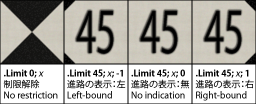
▸ Options for Post:
0: No post will be placed.
1: The post is placed on the right side of the track.
▸ Options for Cource:
0: The post does not indicate a particular direction.
1: The post applies for a right-bound track.
This command defines the new speed limit from this point on. If the new speed limit is lower than the current speed limit, the new speed limit will take effect immediately. If the speed limit is higher than the current speed limit, the new speed limit will take effect only once the whole train has passed this point. By setting Speed to 0, the speed restriction is released. By setting Post to either -1 or 1, a default Japanese-style speed post is placed at the respective side of the track. Setting Course to either -1 or 1 includes a directional indication, which is usually used at railroad switches to indicate that the speed limit only applies if the respective direction is being taken. If Speed is set to 0, the setting of Course has no effect.
This command starts a section, the functional part of signalling, to be used in conjunction with Track.SigF, which creates a visual representation of a section (a signal). The ai parameters specify the aspects the section can bear. An aspect of 0 corresponds to a red section which must not be passed by a train. The a0 term is mandatory.
Default versus simplified section behavior
There are two different modes of behavior on how to interpret the ai parameters. The mode can be set via Options.SectionBehavior. The following are separate descriptions for default and simplified behavior.
Default behavior:
The ai terms specify the aspect the section should bear depending on how many sections ahead are clear until a red one is encountered. The order of the terms is relevant. The same aspect may occur multiple times.
▸ Meanings of the ai terms:
a1: The aspect to show when this section is clear, but the immediately following section is red.
a2: The aspect to show when this section and the following section are clear, but the one immediately following the latter one is red.
an: The aspect to show when n sections are clear before a red one is encountered.
In the case more sections ahead are clear than indicated by the ai terms, the section will bear the aspect of an.
Simplified behavior:
The ai terms specify the repertoire of aspects the section can have. A section will bear the smallest of the ai which is greater than the current aspect of the upcoming section. If no such ai exists, the section will bear the aspect of an. The order of the ai is irrelevant. If the same aspect occurs multiple times, this has no effect.
| Example of a Track.Section command in conjunction with a Track.SigF command: | |
| ▶ |
With Track 1000, .Section 0;2;4, .SigF 3;0;-3;-1 |
Section: A non-negative integer representing the section this signal is attached to, with 0 being the current section, 1 the upcoming section, 2 the section after that, and so on.
X: The X-coordinate to place the signal object, by default measured in meters. The default value is 0.
Y: The Y-coordinate to place the signal object, by default measured in meters. The default value is 0.
Yaw: The angle in degrees by which the object is rotated in the XZ-plane in clock-wise order when viewed from above. The default value is 0.
Pitch: The angle in degrees by which the object is rotated in the YZ-plane in clock-wise order when viewed from the left. The default value is 0.
Roll: The angle in degrees by which the object is rotated in the XY-plane in clock-wise order when viewed from behind. The default value is 0.
This command creates a non-function signal, that is, a visual representation of a section as defined via Track.Section. Setting Y to a negative number resets the y-coordinate to 4.8 meters and attaches a default signal post. Also see Track.Section.
If no object has been defined by Signal(SignalIndex), one of the default Japanese signals is used:
▸ Default signals for SignalIndex:
4: A four-aspect (type A) signal having aspects ●red, ●●yellow-yellow, ●yellow and ●green.
5: A five-aspect (type A) signal having aspects ●red, ●●yellow-yellow, ●yellow, ●●yellow-green and ●green.
6: A repeating signal equivalent to that created by Track.Relay.
Track.Sig Aspects; Unused; X; Y; Yaw; Pitch; Roll
Unused: This argument is not used by openBVE.
X: The X-coordinate to place the signal object, by default measured in meters. The default value is 0.
Y: The Y-coordinate to place the signal object, by default measured in meters. The default value is 0.
Yaw: The angle in degrees by which the object is rotated in the XZ-plane in clock-wise order when viewed from above. The default value is 0.
Pitch: The angle in degrees by which the object is rotated in the YZ-plane in clock-wise order when viewed from the left. The default value is 0.
Roll: The angle in degrees by which the object is rotated in the XY-plane in clock-wise order when viewed from behind. The default value is 0.
▸ Options for Type:
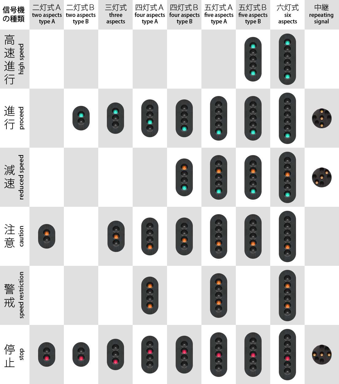
2: A two-aspect (type A) signal having aspects ●red and ●yellow.
-2: A two-aspect (type B) signal having aspects ●red and ●green.
3: A three-aspect signal having aspects ●red, ●yellow and ●green.
4: A four-aspect (type A) signal having aspects ●red, ●●yellow-yellow, ●yellow and ●green.
-4: A four-aspect (type B) signal having aspects ●red, ●yellow, ●●yellow-green and ●green.
5: A five-aspect (type A) signal having aspects ●red, ●●yellow-yellow, ●yellow, ●●yellow-green and ●green.
-5: A five-aspect (type B) signal having aspects ●red, ●yellow, ●●yellow-green, ●green and ●●green-green.
6: A six-aspect signal having aspects ●red, ●●yellow-yellow, ●yellow, ●●yellow-green, ●green and ●●green-green.
This command creates a functional signal. You can choose from the available options for Aspect to create any of the default Japanese signals. Setting X to 0 creates a functional but invisible signal similar to Track.Section. Setting X to a non-zero number and Y to a negative number resets the y-coordinate to 4.8 meters and attaches a default signal post.
| Example of a four-aspect type B signal without a post at x=-3 and y=5: | |
| ▶ | 1000, Track.Signal -4;;-3;5 |
| Example of a four-aspect type B signal including a post at x=-3 and y=4.8: | |
| ▶ | 1000, Track.Signal -4;;-3;-1 |
Track.Signal is similar to using Track.Section and Track.SigF in one command.
Y: The Y-coordinate at which to place the object, by default measured in meters. The default value is 0.
Yaw: The angle in degrees by which the object is rotated in the XZ-plane in clock-wise order when viewed from above. The default value is 0.
Pitch: The angle in degrees by which the object is rotated in the YZ-plane in clock-wise order when viewed from the left. The default value is 0.
Roll: The angle in degrees by which the object is rotated in the XY-plane in clock-wise order when viewed from behind. The default value is 0.
This commands creates a default Japanese repeating signal. The repeating signal repeats the state of the upcoming signal. Setting X to zero does not create a repeating signal, but forces the command to be ignored. Setting X to a non-zero number and Y to a negative number resets the y-coordinate to 4.8 and attaches a default signal post.
● 11.6. Safety systems
BeaconStructureIndex: A non-negative integer representing the object to be placed as defined via Structure.Beacon, or -1 to not place any object.
Section: An integer representing the section to which the beacon is attached, namely 0 for the current section, 1 for the upcoming section, 2 for the section behind that, etc., or -1 for the next red section.
Data: An integer representing arbitrary data specific to the beacon type to be transmitted to the train.
X: The X-coordinate at which to place the object, by default measured in meters. The default value is 0.
Y: The Y-coordinate at which to place the object, by default measured in meters. The default value is 0.
Yaw: The angle in degrees by which the object is rotated in the XZ-plane in clock-wise order when viewed from above. The default value is 0.
Pitch: The angle in degrees by which the object is rotated in the YZ-plane in clock-wise order when viewed from the left. The default value is 0.
Roll: The angle in degrees by which the object is rotated in the XY-plane in clock-wise order when viewed from behind. The default value is 0.
This command places a beacon (transponder). The object must have been loaded via Structure.Beacon(BeaconStructureIndex) prior to using this command. When the train passes the beacon, the type of beacon and various data will be transmitted to the train, including the state of the referenced section.
It should be noted that the built-in safety systems also receive data from these beacons as Track.Beacon(Type) is roughly equivalent to Track.Transponder(Type). Please see the page about beacon standards for more information.
Track.Tr Type; Signal; SwitchSystem; X; Y; Yaw; Pitch; Roll
Signal: The signal this transponder references. The default value is 0.
SwitchSystem: Whether to automatically switch the safety system. The default value is 0.
X: The X-coordinate at which to place the object, by default measured in meters. The default value is 0.
Y: The Y-coordinate at which to place the object, by default measured in meters. The default value is 0.
Yaw: The angle in degrees by which the object is rotated in the XZ-plane in clock-wise order when viewed from above. The default value is 0.
Pitch: The angle in degrees by which the object is rotated in the YZ-plane in clock-wise order when viewed from the left. The default value is 0.
Roll: The angle in degrees by which the object is rotated in the XY-plane in clock-wise order when viewed from behind. The default value is 0.
▸ Options for Type:
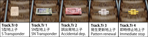
0: An S-type transponder used by ATS-S. Usually placed 600m in front of a signal.
1: An SN-type transponder used by ATS-SN. Usually placed 20m in front of a signal.
2: An accidental departure transponder. Usually placed shortly behind a station stop.
3: An ATS-P pattern renewal transponder. Usually placed 600m, 280m, 180m, 130m, 85m or 50m in front of a signal, depending on the circumstances.
4: An ATS-P immediate stop transponder. Usually placed either 25m or 30m in front of a signal, depending on the circumstances.
▸ Options for Signal:
1: The signal immediately behind the upcoming signal is referenced.
n: The n‘th signal behind the upcoming signal is referenced.
▸ Options for SwitchSystem:
0: The transponder automatically switches the train to ATS-SN for transponder types 0 and 1, and to ATS-P for types 3 and 4.
This command places a transponder, usually for the built-in safety systems ATS-SN or ATS-P. For more information about these systems and their transponders, see the user’s documentation about ATS.
It should be noted that custom safety system plugins also receive data from these transponders as Track.Transponder(Type) is roughly equivalent to Track.Beacon(Type). Please see the page about beacon standards for more information.
➟ Go here to find out more about ATS-SN and ATS-P.
This command places an S-type transponder for the built-in safety system ATS-SN, referencing the upcoming signal, and automatically switching to ATS-SN. The command is equivalent to Track.Tr 0;0;0. See there for more information.
This command places a pattern renewal transponder for the built-in safety system ATS-P, referencing the upcoming signal, and automatically switching to ATS-P. The command is equivalent to Track.Tr 3;0;0. See there for more information.
Speed: A non-negative floating-point number representing the speed restriction, by default measured in km/h.
▸ Options for Type:
1: A permanent speed restriction.
This command defines a speed restriction for the built-in safety system ATS-P.
A temporary speed restriction (Type=0) is to be inserted at the point where the speed restriction should apply. ATS-P will know about this speed restriction in advance and will brake the train so that the train meets the speed restriction at that point. Once the point is passed, the speed restriction no longer applies.
A permanent speed restriction (Type=1) is to be inserted at the point where the speed restriction should apply, however, ATS-P does not know about this limit in advance and will only brake the train from that point on. For a higher degree of realism, insert permanent speed restrictions at the same point as ATS-P transponders. A permanent speed restriction, as the name suggests, is remembered by ATS-P and is only released by a subsequent permanent speed restriction.
This command is equivalent to Track.Pattern 1;Speed. See there for more information.
● 11.7. Miscellaneous
This command defines which background image to show from now on.
This command can only be used at the beginning of a block.
EndingDistance: A floating-point number indicating the end of fog, by default measured in meters. The default value is 0.
RedValue: An integer ranging from 0 to 255 representing the red component of the fog. The default value is 128.
GreenValue: An integer ranging from 0 to 255 representing the green component of the fog. The default value is 128.
BlueValue: An integer ranging from 0 to 255 representing the blue component of the fog. The default value is 128.
This command defines the fog from this point on, or deactivates fog. If fog is to be enabled, StartingDistance must be less than EndingDistance. If fog is to be disabled, StartingDistance must be greater than or equal to EndingDistance.
Fog affects the coloring of objects. Objects before the starting distance appear as-is, objects after the ending distance appear in the fog color, and objects in-between blend linearly between those. The background image is affected by fog as well. For the fog calculations, the background image is assumed to be at 600 meters distance from the camera, regardless of the actual viewing distance.
Depending on Options.FogBehavior, there are two options how this command affects fog from this point on. In block-wise mode, the current fog blends from the beginning of this block to the new settings at the end of this block. The new setting is kept for following blocks. This is the default behavior. In interpolation mode, each Track.Fog command defines a control point for fog, where all of the settings (distances and colors) are interpolated linearly between the control points.
This command can only be used at the beginning of a block.
This command marks a point which affects the brightness in the cab. Value is measured from 0 (dark) to 255 (light), and is linearly interpolated between successive Track.Brightness commands for any given point on the track. This command should be used for tunnels, bridges, station roofs, or anything else that would affect the brightness as perceived inside the cab.
| Example: | |
| ▶ |
With Track 1200, .Brightness 255 ,; before the bridge starts 1205, .Brightness 128 ,; directly under the bridge here 1210, .Brightness 255 ,; as soon as the bridge ends |
Distance: A non-zero floating-point number indicating the length for which the marker image is displayed, by default measured in meters.
▸ Behavior for Distance:
positive value: The marker image starts to display Distance meters before the Track.Marker command, and ends at the Track.Marker command.
This command shows a so-called marker image, which is displayed in the top-right corner of the screen. You can use these images for advisory or informational purposes. The RGB color of 64,64,64 inside the image is made transparent.
A Track.Marker command, linking to a single XML file is also supported. These allow more control over markers than is available in the routefile commands.
These are fully described on the the XML Markers page…
Distance: A non-zero floating-point number indicating the length for which the text is displayed, by default measured in meters.
FontColor: The font color for this marker text
▸ Behavior for Distance:
positive value: The marker image starts to display Distance meters before the Track.Marker command, and ends at the Track.Marker command.
▸ FontColor 的選項:
2: Gray.
3: White.
4: Red.
5: Orange.
6: Green.
7: Blue.
8: Magenta.
This command creates a simple textual marker, which is added to the list of messages in the upper left-hand corner of the screen.
Track.POI RailIndex; X; Y; Yaw; Pitch; Roll; Text
X: A floating-point number representing the horizontal offset from the rail, by default measured in meters. Negative values indicate left, positive ones right.
Y: A floating-point number representing the vertical offset from the rail, by default measured in meters. Negative values indicate below, positive ones above.
Yaw: The angle in degrees by which the view is rotated in the XZ-plane in clock-wise order when viewed from above. The default value is 0.
Pitch: The angle in degrees by which the view is rotated in the YZ-plane in clock-wise order when viewed from the left. The default value is 0.
Roll: The angle in degrees by which the view is rotated in the XY-plane in clock-wise order when viewed from behind. The default value is 0.
Text: A textual representation of the point of interest.
This command creates a point of interest which the user can jump to by pressing the CAMERA_POI_PREVIOUS (NUM 1) or CAMERA_POI_NEXT (NUM 7) keys. The camera will be placed at the specified location with the specified orientation. If Text is non-empty, a message will appear briefly showing the text.
This commands creates a position-time-association for an invisible preceding train in order to influence signalling. Contrary to a real preceding train as created by Route.RunInterval, the invisible preceding train created by Track.PreTrain is a way of scripting where the invisible preceding train is at any given time. The position-time-associations must be in increasing order, that is, at a later track position, the associated time must also be later. Before the first scripted time, the invisible preceding train resides at the first scripted position. In-between the first and last scripted time, the invisible preceding train moves (linearly) between the scripted points. After the last scripted time, the invisible preceding train is removed and thus clears signalling.
Speed: The reference speed in km/h for speed-dependant sounds, or 0 to play the sound speed-independently. The default value is 0.
This command plays an announcement or other kind of sound in the cab once the player’s train crosses the point where this command is used. If Speed is set to 0 (default), the sound is played as-is. If a Speed is given though, the sound plays at is original pitch at the specified speed, and is pitch-modulated proportionally for other speeds, useful for custom flange sounds, pointwork sounds, etc.
X: A floating-point number representing the horizontal offset from rail 0, by default measured in meters. Negative values indicate left, positive ones right.
Y: A floating-point number representing the vertical offset from rail 0, by default measured in meters. Negative values indicate below, positive ones above.
This command places an environmental sound effect at the specified location. The sound will play in a loop for the duration of the simulation and employs the doppler effect. (Note: All sounds in openBVE employ the doppler effect.)
This command places a bumper. The train can collide with the bumper in both the forward and backward directions. Place this command at the beginning and the end of the route. An object is not automatically created, so use Track.FreeObj to create a visual representation of the bumper if necessary.
BeaconStructureIndex: A non-negative integer representing the object to be placed as defined via Structure.Beacon, or -1 to not place any object.
NextDestination: An integer representing the destination value set when passing over this beacon in a forwards direction, or -1 to disable.
PreviousDestination: An integer representing the destination value set when passing over this beacon in a reverse direction, or -1 to disable.
TriggerOnce: If set to 0, this beacon will be triggered by all valid trains which pass over it. If set to 1, it will be triggered by the first valid train only.
X: The X-coordinate at which to place the object, by default measured in meters. The default value is 0.
Y: The Y-coordinate at which to place the object, by default measured in meters. The default value is 0.
Yaw: The angle in degrees by which the object is rotated in the XZ-plane in clock-wise order when viewed from above. The default value is 0.
Pitch: The angle in degrees by which the object is rotated in the YZ-plane in clock-wise order when viewed from the left. The default value is 0.
Roll: The angle in degrees by which the object is rotated in the XY-plane in clock-wise order when viewed from behind. The default value is 0.
This command places a special beacon, which sets the destination variable, available for use by plugins and animated objects. The object must have been loaded via Structure.Beacon(BeaconStructureIndex) prior to using this command.
BeaconStructureIndex: A non-negative integer representing the object to be placed as defined via Structure.Beacon, or -1 to not place any object.
TriggerOnce: If set to 0, this beacon will be triggered by all valid trains which pass over it. If set to 1, it will be triggered by the first valid train only.
X: The X-coordinate at which to place the object, by default measured in meters. The default value is 0.
Y: The Y-coordinate at which to place the object, by default measured in meters. The default value is 0.
Yaw: The angle in degrees by which the object is rotated in the XZ-plane in clock-wise order when viewed from above. The default value is 0.
Pitch: The angle in degrees by which the object is rotated in the YZ-plane in clock-wise order when viewed from the left. The default value is 0.
Roll: The angle in degrees by which the object is rotated in the XY-plane in clock-wise order when viewed from behind. The default value is 0.
This command places a special beacon, which commands an AI driver to play the horn. Both an AI controlled player train and pure AI trains will trigger this beacon, unless TriggerOnce is set. The object must have been loaded via Structure.Beacon(BeaconStructureIndex) prior to using this command.
This command may be used as an alternative to the Route.AmbientLight , Route.DirectionalLight and Route.LightDirection commands.
It allows the lighting to be varied using a time-based model, and is described fully on the following page:
GreenValue: An integer ranging from 0 to 255 representing the green component of the ambient light. The default value is 160.
BlueValue: An integer ranging from 0 to 255 representing the blue component of the ambient light. The default value is 160.
This command defines the ambient light color to be used from this point onwards. All polygons in the scene are illuminated by the ambient light regardless of the light direction.
GreenValue: An integer ranging from 0 to 255 representing the green component of the directional light. The default value is 160.
BlueValue: An integer ranging from 0 to 255 representing the blue component of the directional light. The default value is 160.
This command defines the directional light to be used from this point onwards. The polygons in the scene are only fully illuminated by the directional light if the light direction points at the front faces. If pointing at back faces, no light is contributed. Route.LightDirection should be set to specify the light direction.
Phi: A floating-point number representing the angle in degrees which controls the planar rotation of the light direction. The default value is about -26.57.
This command defines the light direction from this point onwards. This is the direction the light shines at, meaning the opposite direction the sun is located at. First, Theta determines the pitch. A value of 90 represents a downward direction, while a value of -90 represents an upward direction. With those extremes, the value of Phi is irrelevant. A value of 0 for Theta represents a forward direction originating at the horizon behind. Once the pitch is defined by Theta, Phi determines the rotation in the plane. A value of 0 does not rotate, a value of 90 rotates the direction to the right and a value of -90 rotates to the left. A backward direction can be both obtained by setting Theta and Phi to 180 and 0 or to 0 and 180, respectively. Values in-between allow for more precise control of the exact light direction.
The direction of the light is relative to the initial direction at the zero-point of the route (e.g Track position 0), not the current position.
| Converting a spherical direction (theta,phi) into a cartesian direction (x,y,z): | |
| ƒ |
x = cos(theta) * sin(phi) y = -sin(theta) z = cos(theta) * cos(phi) |
| Converting a cartesian direction (x,y,z) into a spherical direction (theta,phi) for y2≠1: | |
| ƒ |
theta = -arctan(y/sqrt(x2+z2)) phi = arctan(z,x) |
| Converting a cartesian direction (x,y,z) into a spherical direction (theta,phi) for y2=1: | |
| ƒ |
theta = -y * pi/2 phi = 0 |
In the formulas above, cos(x) represents the cosine, sin(x) the sine, arctan(x) the inverse tangent, arctan(x,y) the two-argument inverse tangent and sqrt(x) the square root. The formulas can be used to convert between spherical and cartesian coordinates if working with either one seems more intuitive than working with the other one. The formulas also serve as the official documentation on how the light direction is mathematically defined (using radians for the trigonometric functions).