■ Isi
- 1. Overview
- 2. The file identifier
- 3. Syntax
- 4. The Acceleration section
- 5. The Performance section
- 6. The Delay section
- 7. The Move section
- 8. The Brake section
- 9. The Pressure section
- 10. The Handle section
- 11. The Cab section
- 12. The Car section
- 13. The Device section
- 14. The Motor sections
■ 1. Penjelasan
The train.dat file describes the characteristics of trains including acceleration, brake behavior, installed equipment, speed-sound associations, and more.
☀ Tip: Train Editor
You can use the Train Editor to more conveniently edit the train.dat. This page should still be used as a reference. However, you can also edit the train.dat manually if so desired.
The file is a plain text file encoded in any arbitrary encoding, however, UTF-8 with a byte order mark is the preferred choice. The parsing model for numbers is Loose, however, you are encouraged to produce Strict output nonetheless. The file is required to be located inside the train folder and is expected to be named train.dat. The file is interpreted on a per-line basis, from top to bottom.
■ 2. The file identifier
The first line in the train.dat is expected to be an identifier indicating the version of the file format. Allowed values are:
| Version 1.22 is being used: | |
| ▶ |
BVE1200000 BVE1210000 BVE1220000 |
| Version 2.0 is being used (choose either one): | |
| ▶ |
BVE2000000 OPENBVE |
From Version 1.5.3.3 onwards, the OPENBVE identifier may optionally be followed by the minimum version number of openBVE required, e.g.
| openBVE 1.5.3.0 is required: | |
| ▶ | OPENBVE1530 |
Any other value will be reported as being non-supported and version 2.0 will be assumed. The selected version number affects the parsing of the #ACCELERATION section, which is explained later on.
■ 3. Syntax
For each line in the file, white spaces at the beginning and the end of that line are ignored.
Each line in the file after the identifier can mark the beginning of a new section or contain data entries for the last opened section. Empty lines or lines solely consisting of white spaces are not ignored.
A new section is opened by starting the line with a number sign character (U+0023). The text which follows the number sign indicates the name of the section and is case-insensitive. The beginning of a section has thus the following form:
The order in which sections appear within the file is irrelevant. Each line following the opening of a new section is interpreted as a data entry. These data entries are not named, thus their order is important. When a data entry is expected but omitted because a new section was started, a default value will apply. The exact interpretation of each data entry is explained in the following sections, along with default values.
Komentar bisa ditambahkan di mana saja di akhir teks. Tambahkan titik koma " ; " lalu tulis komentar atau catatan yang diinginkan.
■ 4. The Acceleration section
The Acceleration section defines the acceleration characteristics of the train for each individual power notch. The number of notches available in the train can be set inside the Handle section. For each notch, one data entry is expected, starting with the first notch.
This starts the section.
a1: A positive floating-point number representing the acceleration at a speed of v1 expressed in km/h/s.
v1: A positive floating-point number representing a reference speed in km/h corresponding to a1.
v2: A positive floating-point number representing a reference speed in km/h corresponding to e.
e: A positive floating-point number representing an exponent. The behavior is different for version 1.22 and version 2.0 file formats.
This data entry consists of five comma-separated values. White spaces surrounding the values are ignored. The acceleration the motor cars can provide for the whole train (accounting for unpowered trailer cars) at a given speed is calculated as follows:
If the speed of the train is 0 km/h, a0 indicates the acceleration output.
If the speed of the train is between 0 km/h and v1, the acceleration output is determined via the following formula:
| Acceleration between 0 km/h and v1, where x is the current speed of the train in km/h: | |
| ƒ | a0 + (a1 - a0) * x / v1 |
If the speed of the train is v1, the acceleration output is indicated by a1.
If the speed of the train is between v1 and v2, the acceleration output is determined via the following formula:
| Acceleration between v1 and v2, where x is the current speed of the train in km/h: | |
| ƒ | v1 * a1 / x |
If the speed of the train is greater than v2, the acceleration output is determined via the following formula (for version 2.0 exponents):
| For version 2.0: Acceleration above v2, where x is the current speed of the train in km/h: | |
| ƒ | v1 * a1 * v2e-1 / xe |
For a version 1.22 file format, the exponent e is converted into a version 2.0 exponent according to the following equation (and then, the above formula applies):
| Converting a version 1.22 exponent into a version 2.0 exponent: | |
| ƒ | e2.0 = min(1 - v2 * log(e1.22) / log(9/4), 4) |
In the above formula, log denotes the natural logarithm and min the minimum function. Please notice that version 1.22 exponents are clamped at 4 after conversion to a 2.0 exponent.
Please take into account that the effective acceleration will always be lower than specified due to various resistances, including rolling resistance and air resistance.
| Example of an Acceleration section for 4 power notches: | |
| ▶ |
#ACCELERATION 0.77,0.39,7,7,1 1.96,1.96,24,24,3 1.96,1.96,52,52,3.4 1.96,1.96,52,83,2.7 |
■ 5. The Performance section
This section defines the brake performance and coefficients which influence the physics.
This starts the section.
The following spelling variations can be used:
#PERFORMANCE, DECELERATION
A non-negative floating-point number corresponding to the deceleration in km/h/s the service brakes can provide. The corresponding brake cylinder pressure can be defined in the #PRESSURE section. The default value is 1.
A non-negative floating-point number corresponding to the coefficient of static friction, which plays an important role in wheel slip. The coefficient is dimensionless. Normal values for steel on steel range between 0.25 and 0.35. For rubber on steel, normal values range between 0.50 and 0.60. The default value is 0.35.
This value is not currently used by openBVE. Please set to 0.
A non-negative floating-point number corresponding to the coefficient of rolling resistance, which plays an important role in the acceleration performance as it is one of the factors providing a resistance to the attempt of the train to accelerate. The coefficient is dimensionless. The default value is 0.0025.
A non-negative floating-point number corresponding to the aerodynamic drag coefficient, which plays an important role in the acceleration performance as it is one of the factors providing a resistance to the attempt of the train to accelerate. The coefficient is dimensionless. The default value is 1.1.
| Example of a Performance section: | |
| ▶ |
#PERFORMANCE 3.6 0.35 0 0.0025 1.1 |
■ 6. The Delay section
This section defines various delays associated with electric power and electric braking.
This starts the section.
A non-negative floating point number representing the time in seconds (s) before increasing the power notch takes effect. The default value is 0.
A non-negative floating point number representing the time in seconds (s) before decreasing the power notch takes effect. The default value is 0.
A non-negative floating point number representing the time in seconds (s) before increasing the brake notch takes effect. Applies only to trains that have notched brakes. The default value is 0.
A non-negative floating point number representing the time in seconds (s) before decreasing the brake notch takes effect. Applies only to trains that have notched brakes. The default value is 0.
Setting a delay for each notch
From V1.5.3.4 onwards, a comma separated list may be used for any of the above parameters, supplying the delay values from Notch 0 upwards. If this list is shorter than the total number of notches, the last value will be used for all subsequent notches.
| Example of a Delay section: | |
| ▶ |
#DELAY 0.5 0 0.32 0.32 |
■ 7. The Move section
This section defines various jerk values associated with electric power and electric braking, as well as flow rates associated to the physical brake systems.
This starts the section.
A non-negative floating point number representing the jerk in 1/100 meters per second cubed (1/100 m/s3) when the acceleration produced by the engine is increased. The default value is 1000.
A non-negative floating point number representing the jerk in 1/100 meters per second cubed (1/100 m/s3) when the acceleration produced by the engine is decreased. The default value is 1000.
A non-negative floating point number representing the jerk in 1/100 meters per second cubed (1/100 m/s3) when the deceleration produced by the electric brake is increased. Applies only to trains that use the electric brake. The default value is 1000.
A non-negative floating point number representing the jerk in 1/100 meters per second cubed (1/100 m/s3) when the deceleration produced by the electric brake is decreased. Applies only to trains that use the electric brake. The default value is 1000.
A non-negative floating point number representing the mean pressure increase rate of the brake cylinder in kilopascal per second (kPa/s) when the pressure increases due to an emergency brake application. The default value is 300.
A non-negative floating point number representing the mean pressure decrease rate of the brake cylinder in kilopascal per second (kPa/s) when the pressure decreases due to a brake release. The default value is 200.
For a service brake application, a lower value than BrakeCylinderUp will be used.
| Example of a Move section: | |
| ▶ |
#MOVE 500 3000 3000 500 200 160 |
■ 8. The Brake section
This section defines the brake type and other related settings.
This starts the section.
▸ Options for BrakeType:
1: Digital/analog electro-pneumatic air brake without brake pipe (electric command brake)
2: Air brake with partial release feature
This entry defines which brake type to use. If set to 2, the automatic air brake is used which uses a brake pipe across the whole train to supply each car with compressed air and to regulate the brake application. The brake pipe pressure needs time to propagate through the train, and thus, brake applications and releases are not synchronized between the cars. The train will always have separated power and brake handles, and thus, the HandleType entry inside the Handle section will be ignored.
If set to 0, the electromagnetic straight air brake is used which is an enhancement to the automatic air brake. Contrary to the automatic air brake, the brake command is synchronized on all cars electrically, while the brake pipe is still used to distribute compressed air.
If set to 1, the electric command brake is used which does not use the classical brake pipe altogether. Each car is an individual unit having its own brake equipment, while the brake command is synchronized electronically.
▸ Options for BrakeControlSystem:
1: Closing electromagnetic valve (lock-out valve) (締切電磁弁)
2: Delay-including control (遅れ込め制御)
This entry defines which kind of brake control system to use. This setting only applies for the electromagnetic straight air brake and the electric command brake. With those brake systems, the motor of the train helps in braking a train (dynamic braking).
If BrakeControlSystem is set to 0 (none), the motor will always brake in addition to the physical brake, leading to a stronger braking force at all times.
With 1 (closing electromagnetic valve), the pressure to the brake cylinder is interrupted when the train travels above the brake control speed, and the electric brake is used instead. When below the control speed, the physical brake operates normally, while the electric brake is not used.
With 2 (delay-including control), the motor is used to brake the train with the deceleration setting as specified in the Performance section, and if the motor cannot provide this deceleration on its own, the physical brake is additionally used. When the train travels below the brake control speed, the physical brakes are used. However, as the physical brakes need time to fill the brake cylinder, the electric brake is still used to compensate for this delay.
The deceleration that is provided by the electric brake is calculated via the highest acceleration obtained via any of the acceleration curves in the #ACCELERATION section (let’s call it MaximumAcceleration) and the service brake deceleration performance as defined in the #PERFORMANCE section (let’s call it Deceleration) in the following way:
| ƒ | 0.5 * (MaximumAcceleration + Deceleration) |
A non-negative floating-point number measured in kilometers per hour (km/h) at which the brake control system changes operation. The setting is ignored if BrakeType is set to 2 or if BrakeControlSystem is set to 0. See the description for BrakeControlSystem for more information.
| Example of Brake section: | |
| ▶ |
#BRAKE 0 1 10 |
■ 9. The Pressure section
This section defines various pressures for the train brake.
This starts the section.
A positive floating-point number measured in kilopascal (kPa) indicating the brake cylinder pressure corresponding to a full service brake application. The value is required to be less than or equal to BrakeCylinderEmergencyMaximumPressure. The default value is 480.
A positive floating-point number measured in kilopascal (kPa) indicating the brake cylinder pressure corresponding to an emergency brake application. The value is required to be greater than or equal to BrakeCylinderServiceMaximumPressure. The default value is 480.
A positive floating-point number measured in kilopascal (kPa) indicating the pressure in the main reservoir at which the air compressor is activated until the maximum pressure is reached. The default value is 690.
A positive floating-point number measured in kilopascal (kPa) indicating the pressure in the main reservoir at which the air compressor is deactivated. As a consequence, no pressure in either of the brake components can exceed this value. The default value is 780.
Default flow rates for other brake system components
When using a train.dat file the following default flow rates appply between the other components of the brake system:
| Main Compressor | Equalizing Reservoir | Auxiliary Reservoir | Brake Pipe | Straight Air Pipe | |
|---|---|---|---|---|---|
| Charge rate | 5kPa /s | 20kPa /s | 200kPa /s | 1000kPa /s | |
| Normal flow rate | 5kPa /s | 1500kPa /s | 3000kPa /s | ||
| Emergency flow rate | 25kPa /s | 5000kPa /s | 4000kPa /s | ||
| Release rate | 2000kPa /s |
Further control over these may be obtained by using the train.xml format.
Brake cylinder and main reservoir
Note that for all brake systems, the pressure in the brake cylinder can never exceed the highest pressure that can be produced in the main reservoir. As such, setting BrakeCylinderEmergencyMaximumPressure to a higher value than MainReservoirMaximumPressure will result in lower deceleration than set by Deceleration in the Pressure or Deceleration section. If BrakeCylinderEmergencyMaximumPressure is greater than MainReservoirMinimumPressure, there might not be enough pressure available in the main reservoir to obtain a full service or emergency brake application, and also, the brake cylinder might not be exhausted immediately with the automatic air brake and the electromagnetic straight air brake.
A positive floating-point number measured in kilopascal (kPa) indicating the normal pressure in the brake pipe. The default value is chosen to be somewhere between BrakeCylinderEmergencyMaximumPressure and MainReservoirMinimumPressure, ideally 490, if possible.
| Example of a Pressure section: | |
| ▶ |
#PRESSURE 440 440 690 780 490 |
■ 10. The Handle section
This section defines the type of the handle and the amount of power and brake notches.
This starts the section.
▸ Options for HandleType:
1: One combined power and brake handle
2: Separate power and brake handles, but interlocked so that the power setting may not be modified whilst the brake is active 3: Separate power and brake handles, but interlocked so that the reverser setting may not be modified whilst power is applied
This entry defines which kind of handles should be used. If the train uses an automatic air brake (defined in the #BRAKE section), this setting will always be overridden to use two separate handles.
A non-negative integer indicating how many power notches are available. There should be as many entries in the #ACCELERATION section as indicated by PowerNotches.
A non-negative integer indicating how many brake notches are available. The value is ignored for trains using automatic air brakes (defined in the #BRAKE section).
A non-negative integer indicating how many notches the power handle needs to be reduced before an actual change in the power notch setting internally occurs.
☀ Frequently used application:
If the value is set to PowerNotches, the driver needs to reset the power notch to neutral before the power is actually reduced. If the driver wanted to go from power notch P4 to power notch P3, it would be first required to move down to neutral. When going down from P4 over P3, P2 and P1, the internal power output will still resemble power notch P4 during that time. Only once the neutral position is reached will the power output be actually reduced to zero. The driver could then increase the power to P3 as initially desired.
▸ Options for EbHandleBehaviour:
1: The Power handle is returned to neutral.
2: The Reverser handle is returned to neutral.
3: Both the Power and the Reverser handle are returned to neutral.
This entry defines the behavior of the Power and Reverser handles when the Emergency Brake is applied.
Note: Requires openBVE 1.5.3.3 or higher. [Will be silently ignored in older versions]
A non-negative integer indicating how many locomotive brake notches are available.
▸ Options for LocoBrakeType:
1: Independant- The locomotive brakes are independant of the train brakes.
2: Blocking- The locomotive brakes block the release of the train brakes.
A non-negative integer indicating how many power notches are available to the driver.
A non-negative integer indicating how many brake notches are available to the driver.
| Example of a Handle section: | |
| ▶ |
#HANDLE 0 4 8 0 |
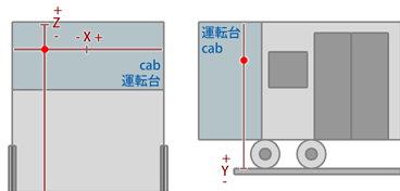
■ 11. The Cab section
This section defines the location of the driver’s eyes inside the train.
This starts the section.
The following spelling variations can be used:
#CAB, #COCKPIT
A floating-point number measured in millimeters (mm) which gives the X-coordinate of the driver’s eye from the center of the driver’s car. Negative values indicate a location on the left side of the train, positive ones on the right side.
A floating-point number measured in millimeters (mm) which gives the Y-coordinate of the driver’s eye from the top of the rails. Negative values indicate a location below the top of the rails, positive ones above the top of the rails.
A floating-point number measured in millimeters (mm) which gives the Z-coordinate of the driver’s eye from the front of the driver’s car. Negative values indicate a location inside the car, positive ones outside.
A non-negative integer indicating which car the driver is located in. The first car in the train has index 0, the second car index 1, and so on.
| Example of a Cab section: | |
| ▶ |
#CAB -900 2750 -1000 0 |
■ 12. The Car section
This section defines the number of cars and their masses.
This starts the section.
A positive floating-point number measured in metric tons (1000 kg) indicating the mass of a single motor car.
A positive integer indicating how many motor cars are available in the train. Only these cars will provide acceleration.
A positive floating-point number measured in metric tons (1000 kg) indicating the mass of a single trailer car. If NumberOfTrailerCars is set to 0, this value will be ignored.
A non-negative integer indicating how many trailer cars are available in the train. These cars are unpowered and thus, they do not contribute to accelerating the train. If FrontCarIsAMotorCar is set to 0, this value is required to be at least 1.
A positive floating-point number measured in meters (m) indicating the length of a car. The number is applied for all the cars in the train, however, this can be overridden by the use of the extensions.cfg file.
▸ Options for FrontCarIsAMotorCar:
1: The front car is a motor car.
Basically, you cannot influence which cars are motor cars and which are trailer cars. However, you can decide on whether the front car (where the driver is located) is a motor car or not, which this entry defines. There is a number of simple setups where the assignment of motor and trailer cars is well defined:
| NumberOfMotorCars | NumberOfTrailerCars | FrontCarIsAMotorCar | Effect |
|---|---|---|---|
| 1 | 0 | 1 | There is only one car, and it’s a motor car. |
| 1 | n | 0 | The rear car is a motor car. All other cars (including the front car) are trailer cars. This corresponds to a locomotive pushing the train from behind. |
| 1 | n | 1 | The front car is a motor car. All other cars are trailer cars. This corresponds to a locomotive pulling the train from the front. |
| 2 | 0 | 1 | There are two cars and both are motor cars. |
| 2 | 1 | 0 | There are three cars. The front car is a trailer car, and the other two cars are motor cars. |
| 2 | 1 | 1 | There are three cars. The front and rear cars are motor cars, and the car in the middle is a trailer car. |
In all other cases, motor cars will be uniformly distributed along the train, but the exact assignment is implementation-specific.
A positive floating-point number measured in meters (m) indicating the width of a car. The number is applied for all the cars in the train. It is primarily used in the calculation of toppling. The default value is 2.6.
A positive floating-point number measured in meters (m) indicating the height of a car. The number is applied for all the cars in the train. The value is not currently used, but will be in the future in the calculation of side winds. The default value is 3.6.
A floating-point number measured in meters (m) indicating height above the rails at which the center of mass is located. The number is applied for all the cars in the train. The value is primarily used in the calculation of derailments. The default value is 1.6.
A positive floating-point number measured in square meters (m2) indicating the frontal area of a car when it is fully exposed to resisting air. This is the case when the car is the front car and the train is driving forward, or the rear car when the train is driving backward. The number is applied to all the cars in the train. The value is primarily used in the calculation of air resistance. Trains usually have a lower frontal area than WidthOfACar * HeightOfACar due to the front being rounded. This is especially true for aerodynamically enhanced trains like Shinkansen. The default value is 0.6 * WidthOfACar * HeightOfACar.
A positive floating-point number measured in square meters (m2) indicating the frontal area of a car when it is not fully exposed to resisting air. This is the case when the car is in the middle of the train and thus surrounded by other cars. The number is applied to all the cars in the train. The value is primarily used in the calculation of air resistance. The default value is 0.2 * WidthOfACar * HeightOfACar.
| Example of a Car section: | |
| ▶ |
#CAR 42 4 36 2 20 0 2.3 3.4 2.6 7.5 1.8 |
■ 13. The Device section
This section defines which devices are present on the train.
This starts the section.
▸ Options for Ats:
0: ATS-SN is available, but ATS-P is not available.
1: ATS-SN and ATS-P are available.
This entry defines which of the default Japanese security systems ATS-SN or ATS-P are available. If the ats.cfg is used, this entry may be without effect depending on the plugin.
▸ Options for Atc:
1: ATC is available but requires manual activation.
2: ATC is available and will automatically activate once transmitting.
This entry defines whether the default Japanese security system ATC is available or not. If available, the user needs to manually activate ATC (1), or the system will automatically activate (2) once the ATC data is transmitting, depending on the setting of Atc. If the ats.cfg is used, this entry may be without effect depending on the plugin.
▸ Options for Eb:
1: The EB device is available.
This entry defines whether the EB device (alerter, or dead-man’s vigilance device) is available or not. If available and the driver does not touch any of the control for 60 seconds, an alarm goes off which needs to be canceled within 5 seconds, or otherwise, an emergency brake application will be performed. If the ats.cfg is used, this entry may be without effect depending on the plugin.
▸ Options for ConstSpeed:
1: The constant speed device is available.
This entry defines whether the constant speed device is available or not. If available, the driver can order to hold the current speed at any time. The device will increase power to hold the current speed despite of inclines and resistances which would normally slow down the train if the power handle was set to neutral. However, the constant speed device will not reduce the speed or even brake on downward gradients.
▸ Options for HoldBrake:
1: The hold brake device is available.
This entry defines whether the hold brake device is available or not. If available, the driver can activate the hold brake, which applies the brakes to hold the current speed on a downward gradient.
▸ Options for ReAdhesionDevice:
0: The readhesion device type A is used.
1: The readhesion device type B is used.
2: The readhesion device type C is used.
3: The readhesion device type D is used.
This entry defines the type of readhesion device to be used. The device tests in certain intervals (reduce interval) whether wheel slip occurs. If so, it reduces the motor output by a certain amount (reduce amount) until the wheels regain adhesion. In certain intervals (increase interval), the device increases the motor output back to normal by a certain amount (increase amount) in order to see whether wheel slip would occur again or not. There are four different types available:
| Type | Reduce interval | Reduce amount | Increase interval | Increase amount | Characteristics |
|---|---|---|---|---|---|
| A | high | instantly zero | medium | very high | Cuts off power instantly and rebuilds it up fast in steps. |
| B | medium | small | high | small | Updates not so often and adapts slowly. Wheel slip can persist longer and power is regained slower. The behavior is smoother. |
| C | medium | medium | medium | medium | The behavior is somewhere in-between type B and type D. |
| D | small | high | small | high | Updates fast and adapts fast. Wheel slip only occurs briefly and power is regained fast. The behavior is more abrupt. |
This entry is not used by openBVE.
▸ Options for PassAlarm:
1: The pass alarm device is available and plays a single time.
2: The pass alarm device is available and plays in a loop.
This entry defines whether the pass alarm device is available or not. If available, the halt.wav located inside the train folder will be played a single time (1) at around 400 m from the beginning of the station, or in a loop (2) until the train opens the doors at the station.
▸ Options for DoorOpenMode:
1: The doors are opened automatically. Manual override is not possible.
2: The doors can only be opened manually.
▸ Options for DoorCloseMode:
1: The doors are closed automatically. Manual override is not possible.
2: The doors can only be closed manually.
| Example of a Device section: | |
| ▶ |
#DEVICE 1 0 1 0 0 2 0 1 2 2 |
■ 14. The Motor sections
These sections define which sounds to play at a given speed for the electric motor and eletric brake, along with associated pitch and volume at that speed. There are four sections called #MOTOR_P1, #MOTOR_P2, #MOTOR_B1 and MOTOR_B2 that control the behavior.
The #MOTOR_P1 and #MOTOR_P2 sections define two independent sounds that can be played at a given time for the electric motor. The #MOTOR_B1 and #MOTOR_B2 sections define two independent sounds that can be played at a given time for the electric brake.
Each section starts with a corresponding #MOTOR_Xi line:
The following entries define the sounds that are to be played at multiples of 0.2 km/h. The first entry corresponds to a speed of 0 km/h, the second entry to a speed of 0.2 km/h, the third entry to a speed of 0.4 km/h, and so on. There can be as many entries as desired. For example, with 800 entries, the 800th entry corresponds to a speed of 159.8 km/h. If the train travels at a higher speed than corresponding to the last entry, this last entry also takes effect for all higher speeds.
An entry inside any of the #MOTOR_Xi sections has the following form:
SoundIndex: A non-negative integer corresponding to the MotorSoundIndex.wav file that is to be played (default sounds), or the SoundIndex=FileName setting in the [Motor] section of the sound.cfg file. SoundIndex may also be -1 in order to indicate that no sound should be played. The default value is -1.
Pitch: A positive floating-point number representing the pitch of the sound in percent. A value of 100 represents an unaltered sound, a value of 200 represents a sound that is played at double speed, a value of 50 represents a sound that is played at half the original speed, and so on. You should avoid values near zero. The default value is 100.
Volume: A non-negative floating-point number representing the volume of the sound. Nominal volume corresponds to a value of 128. The scale of volume is non-linear, and the exact behavior is implementation-specific. The default value is 128.
Please note that the final volume is proportional to the acceleration/deceleration provided by the train. This means that if the motor only outputs a fraction of its maximum acceleration, the final volume of the motor sounds will be reduced. Likewise, if the electric brake only outputs a fraction of its maximum deceleration, the final volume of the electric brake sounds will also be reduced.
| Example of a part of a #MOTOR_P1 section: | |
| ▶ |
#MOTOR_P1 -1,100,36 0,100,36 0,100,35 0,100,35 0,100,34 0,100,34 0,100,33 0,100,33 0,100,32 0,100,32 |