■ Isi
- 1. Overview
- 2. Syntax
- 3. Available commands
- CreateMeshBuilder
- AddVertex
- AddFace
- AddFace2
- Cube
- Cylinder
- Translate, TranslateAll
- Scale, ScaleAll
- Rotate, RotateAll
- Shear, ShearAll
- Mirror, MirrorAll
- SetColor, SetColorAll
- SetEmissiveColor, SetEmissiveColorAll
- SetBlendMode
- SetWrapMode
- LoadTexture
- SetDecalTransparentColor
- EnableCrossfading
- SetTextureCoordinates
■ 1. Penjelasan
A CSV object allows to create a single object by using textual instructions. The object can be used in routes or in trains. The object described by the file can contain any number of individual polygons. The file format allows to group multiple polygons in CreateMeshBuilder sections in which attributes like color or texture information is assigned to all polygons created in each section. This allows for the creation of many polygons in the same CreateMeshBuilder section which share common attributes. A polygon is called a face in this file format.
The file is a plain text file encoded in any arbitrary encoding, however, UTF-8 with a byte order mark is the preferred choice. The parsing model for numbers is Loose, however, you are encouraged to produce Strict output nonetheless. The file name is arbitrary, but must have the extension .csv. The file is interpreted on a per-line basis, from top to bottom.
➟ See also the quick reference for the CSV format…
■ 2. Format penulisan
Setiap baris dalam file ini adalah satu perintah beserta nilai argumennya. Semua sistem penulisan di file ini sama, sebagai berikut:
NameOfTheCommand is case-insensitive. If there are arguments, NameOfTheCommand and Argument1 are separated by a comma (U+002C). Likewise, arguments are also separated by a comma (U+002C). White spaces around the arguments and around the NameOfTheCommand, and well as at the beginning and the end of the line, are ignored. Empty lines or lines solely consisting of white spaces are also ignored.
Arguments may also be omitted by leaving the text at each of the Argumenti blank. A default value will usually apply in this case, which is specific to the command used. All default values are specified in the section of available commands.
Komentar bisa ditambahkan di mana saja di akhir teks. Tambahkan titik koma " ; " lalu tulis komentar atau catatan yang diinginkan.
■ 3. Daftar perintah
This command marks the beginning of a new section of faces. It must precede any of the following commands. There might be as many CreateMeshBuilder sections as desired in the object file. All subsequent commands will then relate to the last CreateMeshBuilder section opened.
vY: The y-coordinate for the vertex in meters. Negative values are down, positive ones up. The default value is 0.
vZ: The z-coordinate for the vertex in meters. Negative values are backward, positive ones forward. The default value is 0.
nX: The x-coordinate for the normal of this vertex. The default value is 0.
nY: The y-coordinate for the normal of this vertex. The default value is 0.
nZ: The z-coordinate for the normal of this vertex. The default value is 0.
This command creates a new vertex which can then be used to create faces via the AddFace or AddFace2 commands. There can be as many AddVertex commands as desired within a CreateMeshBuilder section. However, the order of the vertices given is important for other commands. The first vertex given has index 0, and subsequent vertices have indices 1, 2, 3 and so on.
Normals, atau pencahayaan, berfungsi untuk menentukan arah datangnya cahaya ke mesh ini. Jika semuanya diabaikan atau ditulis 0, maka pengaturan cahaya akan dibuat otomatis. Jika anda menggunakan Normals ini, anda dapat mengatur cahaya yang datang di setiap titik sudut.
This command creates a face given an arbitrary long list of vertex indices. The index corresponds to the order in which the vertices have been created by the AddVertex command, thus the AddFace command needs to be stated after the corresponding AddVertex commands. The first AddVertex command used creates index 0, and subsequent AddVertex commands create indices 1, 2, 3 and so on. The order in which the vertex indices appear is important. They need to be given in clockwise order when looking at the front of the face. The back of the face will not be visible. However, the AddFace2 command can be used to create a face which is visible from both sides. Only convex polygons are supported.
Perintah ini membuat sebuah bangun datar yang terbentuk dari semua Vertex yang telah dimasukan. Urutan penulisan nomor vertex harus berurut sehingga bisa menjadi satu bangun datar. urutan penulisan nomor vertex sesuai arah jarum jam (misalnya kiri bawah, kiri atas, kanan atas, kanan bawah) akan menghasilkan bangun datar menghadap ke depan. bagian belakang bangun datar juga akan terlihat. Namun pada bagian belakang tidak akan terpengaruh oleh pencahayaan.
HalfHeight: A floating-point number representing half the height of the cube in meters.
HalfDepth: A floating-point number representing half the depth of the cube in meters.
This command creates a cube having dimensions as specified by HalfWidth, HalfHeight and HalfDepth. The cube will be centered on the origin (0,0,0). Thus, on the x-axis, the cube extends from -HalfWidth to HalfWidth, on the y-axis from -HalfHeight to HalfHeight and on the z-axis from -HalfDepth to HalfDepth. The cube always has 8 vertices and 6 faces.
Penggambaran perintah Cube
The Cube command is equivalent to a series of AddVertex and AddFace commands, which you need to account for when using other commands in the same CreateMeshBuilder section. The details on what the Cube command does are available here.
UpperRadius: A floating-point number representing the radius for the upper base of the frustum in meters. Can be negative to indicate that the top cap is to be omitted.
LowerRadius: A floating-point number representing the radius for the lower base of the frustum in meters. Can be negative to indicate that the bottom cap is to be omitted.
Height: A floating-point number representing the height of the prism in meters. Can be negative, which will flip the frustum vertically and display it inside-out.
This command creates a frustum. If LowerRadius and UpperRadius are equal, the object generated will reduce to a prism, which can be used as an approximation to the cylinder. If either LowerRadius or UpperRadius are zero, the object generated will reduce to a pyramid. The frustum will be centered on the origin (0,0,0). On the x- and z-axes, the frustum extends from -LowerRadius to LowerRadius for the lower base and from -UpperRadius to UpperRadius for the upper base. On the y-axis, the frustum extends from -1⁄2*Height to 1⁄2*Height.
The number of vertices n will usually suffice to be 6 or 8 when only small radii are used, for example to create a pole. Regardless of the values of UpperRadius, LowerRadius and n, the frustum will always have 2*n vertices, and usually n+2 faces unless any of the caps are omitted. If UpperRadius or LowerRadius are negative, the absolute value is being taken, but the respective caps are not created. If Height is negative, the roles of top and bottom are reversed and the faces will be visible from the inside, while otherwise, they will be visible from the outside.
Representasi tabung
The Cylinder command is equivalent to a series of AddVertex and AddFace commands, which you need to account for when using other commands in the same CreateMeshBuilder section. The details on what the Cylinder command does are available here.
Perintah ini tidak dipakai di openBVE.
TranslateAll, X, Y, Z
Y: A floating-point number representing the translation on the y-coordinate in meters. Negative values translate down, positive ones up. The default value is 0.
Z: A floating-point number representing the translation on the z-coordinate in meters. Negative values translate backward, positive ones forward. The default value is 0.
The Translate command moves all vertices that have been created so far in the CreateMeshBuilder section via the AddVertex, Cube or Cylinder commands. Subsequent vertices are not affected. You can use as many Translate commands as desired in a CreateMeshBuilder section. The TranslateAll command not only affects the vertices generated in the current CreateMeshBuilder section, but also those created in previous CreateMeshBuilder sections. This is useful to insert at the end of the file in order to translate the whole object.
ScaleAll, X, Y, Z
Y: A non-zero floating-point number representing the scale factor on the y-coordinate. The default value is 1.
Z: non-zero A floating-point number representing the scale factor on the z-coordinate. The default value is 1.
The Scale command scales all vertices that have been created so far in the CreateMeshBuilder section via the AddVertex, Cube or Cylinder commands. Subsequent vertices are not affected. You can use as many Scale commands as desired in a CreateMeshBuilder section. The ScaleAll command not only affects the vertices generated in the current CreateMeshBuilder section, but also those created in previous CreateMeshBuilder sections. This is useful to insert at the end of the file in order to scale the whole object.
RotateAll, X, Y, Z, Angle
Y: The y-direction of the rotational axis. Negative values point down, positive ones up. The default value is 0.
Z: The z-direction of the rotational axis. Negative values point backward, positive ones forward. The default value is 0.
The Rotate command rotates all vertices that have been created so far in the current CreateMeshBuilder section via the AddVertex, Cube or Cylinder commands. Subsequent vertices are not affected. The axis of rotation is specified via the X, Y and Z values. Rotation will occur in the plane perpendicular to that direction. A zero vector for this axis is treated as (1,0,0). All other directions are normalized.
You can use as many Rotate commands as desired in a CreateMeshBuilder section. The RotateAll command not only affects the vertices generated in the current CreateMeshBuilder section, but also those created in previous CreateMeshBuilder sections. This is useful to insert at the end of the file in order to rotate the whole object.
ShearAll, dX, dY, dZ, sX, sY, sZ, r
dY: The y-coordinate of the vector D. The default value is 0.
dZ: The z-coordinate of the vector D. The default value is 0.
sX: The x-coordinate of the vector S. The default value is 0.
sY: The y-coordinate of the vector S. The default value is 0.
sZ: The z-coordinate of the vector S. The default value is 0.
r: The ratio that indicates how much to displace vectors. The default value is 0.
The Shear command performs a shear mapping for all vertices that have been created so far in the current CreateMeshBuilder section. The ShearAll command not only affects the vertices generated in the current CreateMeshBuilder section, but also those created in previous CreateMeshBuilder sections. This is useful to insert at the end of the file in order to shear the whole object.
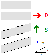
The shear mapping is performed around the origin. Loosely speaking, the object is sliced into planes along the direction D and then displaced along the direction S. Typically, D and S are perpendicular. D and S are always normalized. If Ratio is 0, no transformation is performed. If D and S are perpendicular, a Ratio of 1 corresponds to a slope of 45 degrees.
MirrorAll, X, Y, Z
Y: Whether the y-axis should be mirrored. The default value is 0 (false).
Z: Whether the z-axis should be mirrored. The default value is 0 (false).
The Mirror command mirrors all vertices that have been created so far in the current CreateMeshBuilder section via the AddVertex, Cube or Cylinder commands. Subsequent vertices are not affected. The direction(s) to mirror are specified via the X, Y and Z values. You can use as many Mirror commands as desired in a CreateMeshBuilder section.
The MirrorAll command not only affects the vertices generated in the current CreateMeshBuilder section, but also those created in previous CreateMeshBuilder sections. This is useful to insert at the end of the file in order to mirror the whole object.
SetColorAll, Red, Green, Blue, Alpha
Green: The green component of the color. Measured from 0 (black) to 255 (green). The default value is 255.
Blue: The blue component of the color. Measured from 0 (black) to 255 (blue). The default value is 255.
Alpha: The alpha component of the color. Measured from 0 (transparent) to 255 (opaque). The default value is 255.
The SetColor command sets the color for all faces that were already created in the current CreateMeshBuilder section. If no texture is used, the faces will be colored using the color data as specified by Red, Greenand Blue. If a texture is used, the pixels in the texture will be multiplied by the color, where multiplying with black results in black and multiplying with white does not change the color of the texture pixels. Values in-between make the texture pixels darker. When lighting is used in the route, the actual color can change depending on the lighting conditions, but will usually become darker.
The SetColorAll command sets the color for all faces that were already created in the current CreateMeshBuilder section, and all those created in the previous CreateMeshBuilder sections.
SetEmissiveColorAll, Red, Green, Blue
Green: The green component of the color. Measured from 0 (black) to 255 (green). The default value is 0.
Blue: The blue component of the color. Measured from 0 (black) to 255 (blue). The default value is 0.
The SetEmissiveColor command sets the emissive color for all faces that were already created in the current CreateMeshBuilder section. The difference between the SetColor command and the SetEmissiveColor command is that the SetColor command is affected by lighting, while the SetEmissiveColor command is not. Thus, the SetEmissiveColor command should be used for faces which would emit light themselves, including signals, lamps, windows and the like. The actual color contribution to the faces will be the sum of the light-affected color data and the static emissive color data.
The SetEmissiveColor command sets the emissive color for all faces that were already created in the current CreateMeshBuilder section, and all those created in the previous CreateMeshBuilder sections.
GlowHalfDistance: The distance at which the glow is at 50% of its intensity, measured in meters. The value must be an integer in the range from 1 to 4095, or 0 to disable glow attenuation. The default value is 0.
GlowAttenuationMode: The glow attenuation mode to use. The default is DivideExponent4.
▸ Pilihan tersedia untuk BlendMode:
Additive: The faces are rendered additively.
▸ Pilihan yang bisa dipakai pada GlowAttenuationMode:
DivideExponent4: The glow intensity is determined via the function x4 / (x4 + GlowHalfDistance4), where x is the distance from the camera to the object in meters.
This command sets the blend mode for all faces in the current CreateMeshBuilder section. The Normal mode replaces screen pixels with texture pixels. The Additive mode adds the color of texture pixels to the color of screen pixels, where adding black does not change the screen pixel, while adding white results in white. If GlowHalfDistance is 0, glow attenuation will be disabled, which is the default. If glow attenuation is to be used, GlowHalfDistance represents the distance in meters at which the glow is exactly at 50% of its intensity. When the camera approaches the face, the face will gradually fade out (become transparent). The function used to determine the exact intensity for a given distance can be influenced with the setting of GlowAttenuationMode. DivideExponent2 creates a smoother transition, but will converge to the maximum intensity very slowly, while DivideExponent4 creates a sharper transition which converges more quickly.
▸ Available options for WrapMode:
NighttimeTexture: The file name of the nighttime version of the texture to load, relative to the directory the object file is stored in.
This command loads a texture and uses it for all faces in the current CreateMeshBuilder section. The file name is relative to the directory the object file is stored in. You can use PNG, which supports full alpha channels, but use the alpha channel only if absolutely required as it reduces performance. Prefer using a texture without an alpha channel in conjunction with the SetDecalTransparentColor command in order to use color-key transparency.
If NighttimeTexture is used, it specifies the texture to be used on nighttime lighting conditions, while DaytimeTexture then specifies the texture to be used on daytime lighting conditions. The textures might blend into each other and should be designed accordingly. If NighttimeTexture is used, DaytimeTexture must also be specified. If NighttimeTexture is not used, low lighting conditions will make the daytime version darker. Nighttime textures are meant for use with train interior/exterior objects.
Green: The green component of the color. Measured from 0 (black) to 255 (green). The default value is 0.
Blue: The blue component of the color. Measured from 0 (black) to 255 (blue). The default value is 0.
This command sets the color used for screendoor transparency for all faces that were already created. The texture loaded via the Load command will become transparent for all pixels which match exactly with the color specified via the Red, Green and Blue parameters. The use of screendoor transparency is much more efficient than using a full alpha channel, so prefer using a texture without an alpha channel and use this command instead to make parts of the texture transparent. You need to specify texture coordinates via the Coordinate command in order for the texture to correctly appear on the faces.
This command controls the blending mode when both a daytime and a nighttime texture are specified.
When this is set to false the behavior is as follows:
- The daytime texture is drawn.
- The opacity level for the nighttime texture is calculated from the Track.Brightness value, where a value of 255 produces a fully opaque texture, and a value of 0 produces a fully transparent texture.
- The nighttime texture is drawn.
When this is set to true the behaviour is as follows:
The opacity level for each texture is blended proportionately, so that for example, a Track.Brightness value of 128 would produce an (approximately) 50% blend of each texture and so-on.
X: The x-coordinate of the texture. Integer values correspond to the left/right edge of the texture. If only values between 0 and 1 are to be considered, 0 corresponds to the left and 1 to the right.
Y: The y-coordinate of the texture. Integer values correspond to the top/bottom edge of the texture. If only values between 0 and 1 are to be considered, 0 corresponds to the top and 1 to the bottom.
This command associates a coordinate in the texture to the vertex specified by VertexIndex. The index corresponds to the order in which the vertices have been created by the AddVertex command, thus the Coordinates command needs to be stated after the corresponding AddVertex command. The X and Y values do not necessarily need to be in the range between 0 (left or top) to 1 (right or bottom), but can have any other value. It is assumed in this case that the texture is repeated on an infinite grid where integer values for X and Y correspond to the corners of the texture.