■ 概述
This tool allows to concatenate object segments and to bend the resulting mesh. This is useful to create curved objects such as rails, walls, embankments, etc. The segments can be of B3D or CSV format. You need to be able to provide those segments, meaning you need a basic understanding of the B3D or CSV file formats. See their respective documentation for more information.
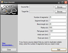
Object Bender comes with a GUI and with a command-line interface. Just start the program without command line arguments to get the GUI. The GUI is useful to familiarize yourself with the program. In the long run, you might want to switch to the command-line interface. See the list of command-line arguments below for that purpose.
Please note that Object Bender always interprets files as UTF-8 unless a byte order mark indicates a different Unicode encoding. Non-Unicode encodings are not supported.
Supported object file formats:
- B3D
- CSV
■ Command-line arguments
| Argument | 含义 |
|---|---|
| /? | Shows the list of command-line arguments. |
| InputFile | The path to the input file. Can be a B3D or CSV file. |
| OutputFile | The path to the output file. Will be of the same format as the input file. |
| /n=Segments | The number of segments. |
| /s=SegmentLength | The length of each segment in meters. |
| /b=BlockLength | The block length in meters. If zero, the object is not rotated for use as a rail object. |
| /r=Radius | The radius in meters. Negative values are left, positive ones right. Zero does not create a curve. |
| /g=RailGauge | The gauge of the rail in millimeters. Only required if cant is applied. |
| /u=InitialCant | The cant at the beginning of the object in millimeters. |
| /v=FinalCant | The cant at the end of the object in millimeters. |
| /a | Appends to the output file instead of overwriting it. |
| ▶ | ObjectBender input.csv output.csv /n=25 /s=1 /b=25 /r=600 |
■ What Object Bender does
Object Bender takes the segment and then creates copies along the z-axis. Each copy is offset by the segment length specified in the GUI or via the command-line interface. The first segment is left unmodified, the second segment shifted on the z-axis by SegmentLength, the third segment by 2SegmentLength, the fourth segment by 3SegmentLength, and so on.
Once the copies have been created, Object Bender performs a polar transformation. In simple words, it means that the z-axis is now bent into a circle where the center of the circle is at coordinates (Radius,0,0), i.e. on the right side for positive values and on the left side for negative values. If a block length was specified, the final object will be additionally rotated so it can be used as a rail object.
Object Bender accepts special markup in the comments of SetTextureCoordinates (CSV) or Coordinates (B3D) commands. These are used to tell Object Bender to shift the texture coordinates by the specified amount for every segment.
| {X=value} | Shifts each segment by value on the x-axis of the texture. |
|---|---|
| {Y=value} | Shifts each segment by value on the y-axis of the texture. |
This markup can be present anywhere in the comments on the same line as the SetTextureCoordinates/Coordinates command. See the tutorial for more details.
■ Tutorial
This is a brief tutorial showing you how to create a curved rail using Object Bender. Aside from the basics, this tutorial will also show you how to work with texture coordinates appropriately, and how to work efficiently with the command-line interface.
● The Basics
Let’s suppose we want to create a curved rail object for a 25 m block length and 1435 mm rail gauge, having a radius of 600 meters and curving to the right. The first thing we need is a short segment of a rail, say 5 meters in length.
| segment.csv | |
| ▶ |
; left rail CreateMeshBuilder AddVertex,-0.7775,0,0 AddVertex,-0.7775,0,5 AddVertex,-0.7175,0,5 AddVertex,-0.7175,0,0 AddFace,0,1,2,3 ; right rail CreateMeshBuilder AddVertex,0.7775,0,0 AddVertex,0.7775,0,5 AddVertex,0.7175,0,5 AddVertex,0.7175,0,0 AddFace,3,2,1,0 ; ballast CreateMeshBuilder AddVertex,-1,-0.2,0 AddVertex,-1,-0.2,5 AddVertex,1,-0.2,5 AddVertex,1,-0.2,0 AddFace,0,1,2,3 SetColor,150,125,100 |
The above code does not use any textures, making things a little simpler for now. We can now open the GUI, select the input file (segment.csv), then set up the parameters we need. Given that our segment is 5 meters in length and our block length is 25 meters, we need 5 copies of the segment to fill out the block, hence:
Number of segments: 5
Segment length: 5
Block length: 25
Radius: 600
Providing the rail gauge is not necessary because we don’t want to employ any cant. We can now select the target file, for example right_curve_600.csv and hit the Start button. This should bring up the simple Done! message. We could now additionally create a left curve with the same settings by simply changing the Radius to -600, select a different output file, for example left_curve_600.csv, and hitting the Start button again.
● Working with texture coordinates
Let’s suppose our ballast is not of a solid color, but uses an appropriate texture, for example:
| segment.csv | |
| ▶ |
; ballast CreateMeshBuilder AddVertex,-1,-0.2,0 AddVertex,-1,-0.2,5 AddVertex,1,-0.2,5 AddVertex,1,-0.2,0 AddFace,0,1,2,3 LoadTexture,ballast.png SetTextureCoordinates,0,0,0 SetTextureCoordinates,1,0,1 SetTextureCoordinates,2,1,1 SetTextureCoordinates,3,1,0 |
It should be noted that the texture’s y-axis in the above code corresponds to the spatial z-axis. If we now picture that the object is copied along the z-axis, we will get one copy of the texture for every segment, i.e. one copy every 5 meters. This can be desired, but let’s suppose we designed the texture to fit a whole 25 meter block. In this case, one segment should not display the whole texture, but just 1/5 of it. For this purpose, we first need to make the segment appear correct on its own:
| segment.csv | |
| ▶ |
; ballast CreateMeshBuilder AddVertex,-1,-0.2,0 AddVertex,-1,-0.2,5 AddVertex,1,-0.2,5 AddVertex,1,-0.2,0 AddFace,0,1,2,3 LoadTexture,ballast.png SetTextureCoordinates,0,0,0.0 SetTextureCoordinates,1,0,0.2 SetTextureCoordinates,2,1,0.2 SetTextureCoordinates,3,1,0.0 |
In the above code, the texture is only shown to 1/5 (=0.2). If we now used Object Bender to concatenate multiple segments to form a longer object, then every segment in the resulting object would show the first fifth of the texture. This is of course undesired. What we need is for every segment to be shifted by 0.2 on the texture’s y-axis. Object Bender accepts special markup for this purpose in the comments of the SetTextureCoordinates command, so let’s add it:
| segment.csv | |
| ▶ |
; ballast CreateMeshBuilder AddVertex,-1,-0.2,0 AddVertex,-1,-0.2,5 AddVertex,1,-0.2,5 AddVertex,1,-0.2,0 AddFace,0,1,2,3 LoadTexture,ballast.png SetTextureCoordinates,0,0,0.0 ; {Y=0.2} SetTextureCoordinates,1,0,0.2 ; {Y=0.2} SetTextureCoordinates,2,1,0.2 ; {Y=0.2} SetTextureCoordinates,3,1,0.0 ; {Y=0.2} |
Now, Object Bender knows that for every of the above four lines of SetTextureCoordinates, each segment should be added 0.2 in the y-values, hence the first segment is unmodified, the second segment will employ the range of 0.2 to 0.4 in the y-values, the third segment 0.4 to 0.6, the fourth segment 0.6 to 0.8, and the final segment 0.8 to 1.0. This makes the texture repeat every 5 segments. With a segment length of 5 meters, that’s every 25 meters, which is our block length.
● Using the command-line interface
Let’s suppose our curved rail object should embed an overhead wire. The overhead wire should not be curved, hence it should be a single 25 meter long wire. We cannot do this in a single step because if we included an overhead wire in our segment.csv, this would get copied and bent, too. Instead, we create both objects separately and join them together later. In order to create our curved rail via the command-line interface, we enter the following code in a terminal:
| Terminal | |
| ▶ | ObjectBender segment.csv right_curve_600.csv /n=5 /s=5 /b=25 /r=600 |
Now, let’s create the overhead wire in a file called
| wire.csv | |
| ▶ |
AddVertex,-0.03,5,0 AddVertex,-0.03,5,25 AddVertex,0.03,5,25 AddVertex,0.03,5,0 AddFace,3,2,1,0 SetColor,0,0,0 |
The above code is a single 25 meter long wire. Given that the object already is 25 meters long, we don’t need to create additional copies, just a single segment. This should be added to our right_curve_600.csv. We can do this in the following way:
| Terminal | |
| ▶ | ObjectBender wire.csv right_curve_600.csv /n=1 /s=25 /b=25 /r=600 /a |
The final /a switch tells Object Bender to append the resulting wire to the target file, not to overwrite it. Let’s combine the terminal code in a batch file. On Windows, this file could be called
| start.bat | |
| ▶ |
ObjectBender segment.csv right_curve_600.csv /n=5 /s=5 /b=25 /r=600 ObjectBender wire.csv right_curve_600.csv /n=1 /s=25 /b=25 /r=600 /a |
If you want to make changes to the segment or to the wire objects, just execute the batch file any time later to get refreshed results. You can also create longer batch file to create left and right curves of different radii this way:
| start.bat | |
| ▶ |
; 300m left ObjectBender segment.csv left_curve_300.csv /n=5 /s=5 /b=25 /r=-300 ObjectBender wire.csv left_curve_300.csv /n=1 /s=25 /b=25 /r=-300 /a ; 300m right ObjectBender segment.csv right_curve_300.csv /n=5 /s=5 /b=25 /r=300 ObjectBender wire.csv right_curve_300.csv /n=1 /s=25 /b=25 /r=300 /a ; 600m left ObjectBender segment.csv left_curve_600.csv /n=5 /s=5 /b=25 /r=-600 ObjectBender wire.csv left_curve_600.csv /n=1 /s=25 /b=25 /r=-600 /a ; 600m right ObjectBender segment.csv right_curve_600.csv /n=5 /s=5 /b=25 /r=600 ObjectBender wire.csv right_curve_600.csv /n=1 /s=25 /b=25 /r=600 /a |
You hopefully get the idea.